ABSTRACT
CFRP (Carbon fiber reinforced plastic) has been widely used in different industries such as aerospace, automobile, sports and medical. Laser processing of CFRP has a great potential for industrial applications. In this paper researched the micro cutting and drilling of CFRP with 0.5 mm thickness using 1064 nm ytterbium nanosecond pulsed fiber laser. It also investigated machining characteristics of micro cutting and drilling according to laser power, frequency, scan speed and number of scan (or irradiation). Complete cutting and through-hole drilling were achieved with low frequency when the laser power was low and with low and middle frequency when the laser power increased. However, those were not achieved a frequency of 100 kHz. The cutting width increased when the power increased and decreased when the frequency and the scan speed increased. The hole size increased when the power and the number of irradiation increased and decreased when the frequency increased. In the case of micro hole array, the hole was blocked during the next hole machining when the hole spacing was narrow. The resin was melted by the heat thus blocking the pre-drilled hole. We devised the laser scan method, and the micro hole array with narrow hole spacing was fabricated successfully.
-
KEYWORDS: CFRP, Fiber laser, Laser micro machining, Micro hole array
-
KEYWORDS: 탄소섬유강화플라스틱, 파이버 레이저, 레이저 미세가공, 미세 구멍열
1. 서론
탄소섬유강화플라스틱(CFRP)은 탄소섬유와 레진이 결합되어 있는 복합소재로, 고강도, 경량, 높은 내구성 등 우수한 특성으로 인해 항공, 자동차, 스포츠, 의료 등 다양한 산업분야에서 활용도가 점차 증가하고 있다.
1 CFRP 제조과정은 1차 성형단계 후 최종제품형상을 얻기 위해 2차 가공작업을 거치게 된다. CFRP 가공법으로는 일반적으로 드릴링, 밀링과 같은 절삭가공이 사용된다. 하지만 CFRP를 구성하는 탄소섬유와 레진의 상이한 특성, 적층구조에 따른 이방성 등으로 인해 정밀가공에 많은 어려움이 있다. 대표적으로 공구마모, 섬유 미절삭, 층간박리, 뜯김, 열손상 등의 문제가 있다.
2,3 따라서, 절삭가공의 문제점을 개선하려는 노력과 함께 절삭가공 외 다양한 CFRP 가공법도 활발히 연구되고 있다. 대표적으로 워터젯,
4 방전가공,
5 레이저
6 등의 특수가공법이 CFRP 가공에 적용되고 있다. 이 중에서, 레이저를 이용한 CFRP 가공은 높은 생산성을 가지며, 대면적 절단
6에서부터 드릴링,
7 미세가공
8에 이르기까지 다양한 분야에 적용가능하여 산업적 활용가치가 높다. 최근 제품 소형화 추세에 따라 레이저를 이용한 CFRP 미세가공에 대한 수요가 커지고 있다. 레이저를 이용하여 CFRP에 정밀한 미세형상을 얻기 위해서는 피코초 단위의 초단펄스
8를 이용하는데, 펄스가 짧을수록 미세가공에는 유리하지만 고가의 장비 가격이 단점이 된다. 최근 경제적인 나노초 파이버 레이저가 금속의 미세가공에 활용되고 있다.
9 나노초 파이버 레이저는 수십에서 수백 마이크로미터 크기의 미세형상가공에 활용가능하며, 또한 경제적이다. 하지만 가공부 주변에 열손상이 발생한다. 열에 약한 레진의 특성으로 인해 나노초 펄스 레이저를 CFRP의 미세가공에 적용하는 시도가 거의 없었다. 따라서 나노초 펄스 레이저를 CFRP 미세가공에 활용하는 것의 가능성, 문제점, 해결방안 등을 연구하는 것이 필요하다. 구체적으로, 가공특성, 열손상 영향, 그리고 이를 최소화하는 방법에 대한 연구가 필요하다. 본 논문에서는 나노초 파이버 레이저를 이용한 CFRP의 미세 절단 및 구멍가공 특성에 대해 살펴보고, 열손상을 최소화하여 우수한 형상정밀도를 갖는 미세 구멍열 가공 방법을 제안한다.
2. 실험장치
본 실험에 사용된 레이저는 20W 출력의 1064 nm 파장을 갖는 Ytterbium Pulsed Fiber Laser(모델명: K2 Fiber 20, 제조사: K2 Laser System)로 일반적으로 레이저 마킹기로 활용되고 있다. 제조사에서 권장하는 레이저 조건은 출력은 최대 20W를 기준으로 10-95%, 주파수는 최대 200 kHz, 스캔속도는 최대 3,000 mm/s이다. 제조사에서 제공하는 전용 소프트웨어(소프트웨어명: Marking Mate)를 이용하였으며, 출력, 주파수, 스캔속도, 반복횟수를 변경할 수 있다. 반복횟수는 절단가공과 구멍가공의 경우를 구분하여 나타내었다. 절단가공의 경우에는 반복스캔횟수(Number of Scan)로, 구멍가공의 경우에는 반복조사횟수(Number of Irradiation)로 나타내었다.
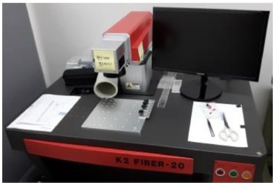
Fig. 1은 본 실험에 사용된 레이저이다.
Fig. 1 1064 nm ytterbium pulsed fiber laser (Model: K2 Fiber 20, Manufacturer: K2 Laser System)

본 실험에서 CFRP는 일방향 시편(UD Type)과 평직직물 시편(Plain Woven Type) 2가지를 사용하였다(제조사: 무한카본). CFRP 시편은 20 × 20 mm 크기로 절단하여 사용하였고, 두께는 0.5 mm이다.
3. 레이저 가공조건에 따른 미세 절단 가공
3.1 가공조건
레이저의 출력(Power), 주파수(Frequency), 스캔속도(Scan Speed)를 변화시키면서 CFRP에 직선을 가공하여 가공특성을 살펴보았다. 실험에 사용된 레이저는 최대출력이 20W인 마킹용이기 때문에 0.5 mm 두께의 CFRP 시편을 절단하기 위해서는 레이저를 1회 조사하는 것으로는 부족하고 반복조사가 필요하다. 본 실험에서는 반복스캔횟수를 100회로 고정하였다. 세부적인 가공조건은
Table 1에 나타내었다.
Table 1Laser micro cutting conditions
Table 1
|
Parameters |
Values |
Remark |
|
Power (%) |
40, 60, 80, 95 |
Max. power: 20 W |
|
Freq. (kHz) |
20, 30, 40, 50, 100 |
Pulse duration: 100 ns |
|
Scan speed (mm/s) |
300, 500, 1000, 1500 |
|
|
No. of scan |
100 |
Fixed |
Fig. 2는 출력 40%, 주파수 50 kHz, 스캔속도 1000 mm/s, 반복스캔횟수 100회의 조건으로 일방향 시편과 평직직물 시편에 직선가공을 수행한 결과이다. 일방향 시편의 경우 탄소섬유방향과 가공방향(레이저 스캔방향)이 수직이 되게 하였다. 즉, 탄소섬유방향은 세로이고, 가공방향(레이저 스캔방향)은 가로방향이다.
Fig. 2(a)와 같이 균일한 선폭으로 가공된 것을 볼 수 있다. 평직직물 시편의 경우에는 체크무늬 모양으로 탄소섬유가 교차하는데, 섬유가 교차하는 부분(
Fig. 2(b)의 가운데 부분)은 가공이 잘 되지 않고 불규칙함을 볼 수 있다. 따라서 레이저 조건에 따른 미세 절단 가공 실험은 일방향 시편을 사용하였다.
Fig. 2Laser micro cutting results according to CFRP type: (a) UD type, (b) Plain woven type (Power 40%, Freq. 50 kHz, Scan speed 1000 mm/s, No. of scan 100)
3.2 가공결과
3.2.1 가공형상
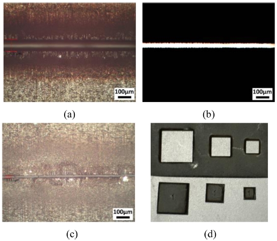
Fig. 3은 일방향 CFRP의 레이저 절단 가공면을 보여준다. 레이저 조건은 출력 95%, 주파수 20 kHz, 스캔속도 300 mm/s, 반복스캔횟수 100회이다.
Fig. 3(a)에서 볼 수 있듯이 가공부 주변으로 가공폭(Cutting Width)보다 넓게 짙은 갈색의 열영향층을 볼 수 있다. 위의
Fig. 2의 조건에서는 가공면 주변으로 열영향층이 많이 생기지 않으나 완전히 절단이 되지 않는다.
Fig. 3(b)는 현미경의 투과조명(Transmitted Illumination)을 이용하여 아래에서 빛을 비춰준 것으로 시편이 절단되었음을 쉽게 알 수 있다.
Fig. 3(c)는 뒷면을 보여준다. 앞면의 가공폭은 94.5 μm이고, 뒷면은 17.17 μm로 절단면이 테이퍼 형상임을 알 수 있다.
Fig. 3(d)는 다양한 크기의 사각형 모양을 절단한 예를 보여준다. 사각형 한 변의 길이는 왼쪽부터 5, 3, 2 mm이다.
Fig. 3Laser micro cutting using UD type CFRP: (a) top view, (b) top view (by transmitted illumination), (c) bottom view, and (d) rectangular shape cutting (side length: 5, 3, 2 mm from left) (Laser: Power 95%, Freq. 20 kHz, Scan speed 300 mm/s, No. of scan 100)

Table 2는 출력, 주파수, 스캔속도 변화에 대한 직선가공 시, 앞면 가공폭(Cutting Width)과 뒷면 가공폭을 나타낸다. 실험은 동일한 조건으로 3회 반복하였으며 가공폭은 평균값으로 나타냈다. 가공폭 뒷면의 값이 없는 것은 절단이 되지 않았음을 의미한다.
Table 2Laser micro cutting results according to power, frequency and scan speed
Table 2
|
No. |
Power
(%) |
Freq.
(kHz) |
Scan
speed
(mm/s) |
Cutting width
(μm) |
No. |
Power
(%) |
Freq.
(kHz) |
Scan
speed
(mm/s) |
Cutting width
(μm) |
No. |
Power
(%) |
Freq.
(kHz) |
Scan
speed
(mm/s) |
Cutting width
(μm) |
|
Front |
Back |
Front |
Back |
Front |
Back |
|
1 |
40 |
20 |
300 |
63.34 |
- |
28 |
60 |
30 |
1500 |
70.14 |
- |
55 |
80 |
50 |
1000 |
67.20 |
- |
|
2 |
40 |
20 |
500 |
59.63 |
- |
29 |
60 |
40 |
300 |
69.41 |
- |
56 |
80 |
50 |
1500 |
65.70 |
- |
|
3 |
40 |
20 |
1000 |
64.21 |
- |
30 |
60 |
40 |
500 |
68.21 |
- |
57 |
80 |
100 |
300 |
66.21 |
- |
|
4 |
40 |
20 |
1500 |
62.94 |
- |
31 |
60 |
40 |
1000 |
66.03 |
- |
58 |
80 |
100 |
500 |
64.18 |
- |
|
5 |
40 |
30 |
300 |
67.72 |
- |
32 |
60 |
40 |
1500 |
66.69 |
- |
59 |
80 |
100 |
1000 |
59.97 |
- |
|
6 |
40 |
30 |
500 |
61.15 |
- |
33 |
60 |
50 |
300 |
67.55 |
- |
60 |
80 |
100 |
1500 |
59.30 |
- |
|
7 |
40 |
30 |
1000 |
62.12 |
- |
34 |
60 |
50 |
500 |
65.19 |
- |
61 |
95 |
20 |
300 |
97.72 |
22.38 |
|
8 |
40 |
30 |
1500 |
59.99 |
- |
35 |
60 |
50 |
1000 |
63.33 |
- |
62 |
95 |
20 |
500 |
86.09 |
23.17 |
|
9 |
40 |
40 |
300 |
59.82 |
- |
36 |
60 |
50 |
1500 |
61.30 |
- |
63 |
95 |
20 |
1000 |
82.37 |
27.99 |
|
10 |
40 |
40 |
500 |
58.97 |
- |
37 |
60 |
100 |
300 |
61.82 |
- |
64 |
95 |
20 |
1500 |
82.21 |
28.32 |
|
11 |
40 |
40 |
1000 |
59.97 |
- |
38 |
60 |
100 |
500 |
57.77 |
- |
65 |
95 |
30 |
300 |
85.40 |
16.33 |
|
12 |
40 |
40 |
1500 |
58.62 |
- |
39 |
60 |
100 |
1000 |
56.86 |
- |
66 |
95 |
30 |
500 |
79.67 |
17.01 |
|
13 |
40 |
50 |
300 |
55.09 |
- |
40 |
60 |
100 |
1500 |
55.39 |
- |
67 |
95 |
30 |
1000 |
82.21 |
24.73 |
|
14 |
40 |
50 |
500 |
55.93 |
- |
41 |
80 |
20 |
300 |
86.94 |
19.02 |
68 |
95 |
30 |
1500 |
79.02 |
27.96 |
|
15 |
40 |
50 |
1000 |
53.07 |
- |
42 |
80 |
20 |
500 |
80.67 |
22.41 |
69 |
95 |
40 |
300 |
81.70 |
27.41 |
|
16 |
40 |
50 |
1500 |
52.43 |
- |
43 |
80 |
20 |
1000 |
83.46 |
23.54 |
70 |
95 |
40 |
500 |
80.87 |
16.86 |
|
17 |
40 |
100 |
300 |
52.72 |
- |
44 |
80 |
20 |
1500 |
80.70 |
26.15 |
71 |
95 |
40 |
1000 |
73.96 |
18.52 |
|
18 |
40 |
100 |
500 |
50.03 |
- |
45 |
80 |
30 |
300 |
82.03 |
22.22 |
72 |
95 |
40 |
1500 |
78.01 |
20.57 |
|
19 |
40 |
100 |
1000 |
48.51 |
- |
46 |
80 |
30 |
500 |
79.17 |
16.01 |
73 |
95 |
50 |
300 |
75.80 |
15.91 |
|
20 |
40 |
100 |
1500 |
45.48 |
- |
47 |
80 |
30 |
1000 |
77.85 |
19.71 |
74 |
95 |
50 |
500 |
74.57 |
18.91 |
|
21 |
60 |
20 |
300 |
80.52 |
21.42 |
48 |
80 |
30 |
1500 |
76.14 |
23.18 |
75 |
95 |
50 |
1000 |
70.19 |
18.23 |
|
22 |
60 |
20 |
500 |
73.44 |
19.04 |
49 |
80 |
40 |
300 |
83.71 |
26.57 |
76 |
95 |
50 |
1500 |
69.07 |
19.84 |
|
23 |
60 |
20 |
1000 |
76.03 |
25.78 |
50 |
80 |
40 |
500 |
75.94 |
16.86 |
77 |
95 |
100 |
300 |
69.06 |
- |
|
24 |
60 |
20 |
1500 |
74.47 |
19.01 |
51 |
80 |
40 |
1000 |
69.90 |
19.88 |
78 |
95 |
100 |
500 |
66.37 |
- |
|
25 |
60 |
30 |
300 |
72.95 |
- |
52 |
80 |
40 |
1500 |
72.27 |
20.71 |
79 |
95 |
100 |
1000 |
63.98 |
- |
|
26 |
60 |
30 |
500 |
67.71 |
- |
53 |
80 |
50 |
300 |
75.63 |
- |
80 |
95 |
100 |
1500 |
63.98 |
- |
|
27 |
60 |
30 |
1000 |
69.91 |
- |
54 |
80 |
50 |
500 |
72.60 |
- |
|
|
|
|
|
|
3.2.2 절단특성
레이저 출력이 40%(8 W)인 경우에는 어떠한 경우에도 뒷면까지 절단되지 않았다. 0.5 mm 두께의 CFRP를 절단하기에는 출력이 부족하였음을 알 수 있다. 출력이 60%로 증가하면 주파수 20 kHz인 경우에 뒷면까지 절단되었다. 출력이 80%로 증가하면, 주파수 20, 30, 40 kHz인 경우에 절단되었으며, 출력이 95%면 주파수 20, 30, 40, 50 kHz인 경우에 절단되었다. 즉, 출력이 증가하면 비교적 높은 주파수에서도 절단됨을 알 수 있다. 실험에 사용된 레이저는 펄스폭이 100 ns이므로, 주파수가 증가하면 펄스휴지시간이 감소한다. 펄스휴지시간동안 재응고층 형성 및 가공부스러기 배출 등의 작용이 일어나므로 적절한 펄스휴지시간이 필요한데, 주파수가 증가하면 펄스휴지시간이 감소하여 가공능력이 떨어지게 된다. 하지만 출력이 증가하면 주파수가 높은 경우에도 절단가공이 가능하게 된다.
3.2.3 가공폭 크기 변화
Fig. 4는
Table 2의 실험결과 일부를 그래프로 나타낸 것이다. 스캔속도 300, 1000 mm/s인 경우에 레이저 출력과 주파수 변화에 따른 가공폭(앞면) 크기를 나타내었다. 출력이 증가함에 따라 가공폭이 커지는 것을 알 수 있으며, 주파수가 증가하면 가공폭이 작아지는 것을 알 수 있다. 전술한 바와 같이 주파수가 증가하면 펄스휴지시간이 짧아진다. 짤은 펄스휴지시간동안에는 재응고층 형성, 부스러기 배출 등이 원활하지 못해 가공능력이 떨어진다. 따라서 가공폭이 작아지고 깊이방향으로 가공이 어려워 완벽히 절단되지 못한다.
Fig. 4Cutting width (front) variation according to laser power
Fig. 5는 레이저 출력 80, 95%인 경우에 레이저 스캔속도에 따른 가공폭(앞면) 크기를 나타내었다. 스캔속도가 증가하면 가공폭이 감소하는 것을 알 수 있다.
Fig. 5Cutting width (front) variation according to laser scan speed
4. 레이저 가공조건에 따른 미세 구멍 가공
4.1 가공조건
CFRP 시편에 미세 구멍을 가공하기 위하여 한 점에 레이저를 반복조사하는 방식을 사용하였다. 절단가공과는 다르게 미세 구멍가공에서는 스캔속도는 고려되지 않는다. 레이저 출력, 주파수, 반복조사횟수(Number of Irradiation) 변화에 따른 미세 구멍 가공특성을 살펴보았다. 세부적인 가공조건은
Table 3에 나타내었다.
Table 3Laser micro drilling conditions
Table 3
|
Parameters |
Values |
Remark |
|
Power (%) |
60, 80, 95 |
Max. power: 20 W |
|
Freq. (kHz) |
20, 50, 100 |
Pulse duration: 100 ns |
|
No. of irradiation |
50, 100, 200, 300, 400, 500 |
|
미세 구멍 가공은 절단가공과는 다르게 한 점에 레이저빔을 반복조사하므로 CFRP시편 종류에 영향을 덜 받는다. 미세 구멍가공 실험에서는 0.5 mm 두께의 평직직물 CFRP 시편을 사용하였다.
4.2 가공결과
4.2.1 가공형상
Fig. 6은 미세 구멍 가공 결과를 보여준다. 레이저 조건은 출력 80%, 주파수 20 kHz, 반복조사횟수 400회이다.
Fig. 6(a)를 보면, 입구 주변에 열에 의해 표면 레진층이 녹은 것이 관찰된다.
Fig. 6(b)는 투과조명을 이용하여 시편 아래쪽에서 빛을 쏴서 구멍이 관통되었음을 보여준다.
Fig 6(c)는 구멍 출구를 보여준다. 구멍 입구 크기는 90.68 μm이고 출구 크기는 16.92 μm로 테이퍼 형상으로 가공되었음을 알 수 있다.
Fig. 6Laser micro drilling results: (a) top view, (b) top view (by transmitted illumination), and (c) bottom view (Laser: power 80%, Freq. 20 kHz, No. of irradiation 400)
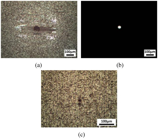
Table 4는 레이저 조건에 따른 미세 구멍의 입구, 출구 크기(Hole Entrance, Hole Exit)를 나타내었다. 레이저 미세 구멍은 크기가 작고 진원도 아니므로 측정에 어려움이 있다. 특히, 뒷면의 구멍 출구부는 크기가 10 μm 정도로 매우 작아서 더 측정하기 어렵다. 따라서 실험결과의 신뢰성을 높이기 위해서 동일한 조건에서 6회 반복실험을 하였고, 평균값을 사용하였다. 관통횟수는 총 6번 반복실험 중에 구멍관통횟수를 나타낸 것이다.
Table 4에서 Through Hole 항목의 Count에 해당한다. 이 때 현미경의 투과조명(Transmitted Illumination)을 사용하였는데, 시편 아래에서 빛을 쏴서 구멍의 관통여부를 확인하는 방법이다. 관통율은 총 6번 반복실험 중 관통횟수를 % 단위로 나타낸 것이다.
Table 4에서 Through Hole 항목의 Rate(%)에 해당한다. 출구 측정횟수(No. of Measurement of Hole Exit)는 현미경으로 구멍의 출구를 관찰하는 방식으로 이 때 출구의 크기를 측정하였다. 투과조명을 사용하여 관통되었음을 확인하였어도, 실제 출구를 측정하는 경우에 구멍의 크기가 매우 작고 형상이 불규칙하여 측정이 불가능한 경우도 있다. 이러한 경우에 관통횟수보다 출구 측정횟수가 더 적다. 예를 들어, 5번의 레이저 조건은 출력 60%, 주파수 20 kHz, 반복조사횟수 400번이며, 구멍크기(입구) 77.42 μm는 6회 반복실험한 6개 구멍 크기의 평균값이다. 관통횟수(Through-Hole Count)는 4인데, 이것은 6회 반복실험 중 4번 구멍이 관통되었다는 뜻이다. 관통율(Through-Hole Rate)은 아래의 식과 같이 계산된다.
Table 4Laser micro drilling results according to power, frequency and number of scan
Table 4
|
No. |
Power
(%) |
Freq.
(kHz) |
No. of
irradiation |
Hole
entrance
(μm) |
Hole
exit
(μm) |
Through hole
(by transmitted
illumination) |
No. of
measurement
of hole exit |
No. |
Power
(%) |
Freq.
(kHz) |
No. of
irradiation |
Hole
entrance
(μm) |
Hole
exit
(μm) |
Through hole
(by transmitted
illumination) |
No. of
measure
ment of
hole
exit |
|
Count |
Rate
(%) |
Count |
Rate
(%) |
|
1 |
60 |
20 |
50 |
71.54 |
- |
0 |
0.0 |
0 |
28 |
80 |
50 |
300 |
80.14 |
11.44 |
5 |
83.3 |
2 |
|
2 |
60 |
20 |
100 |
77.59 |
- |
0 |
0.0 |
0 |
29 |
80 |
50 |
400 |
78.3 |
14.18 |
6 |
100.0 |
2 |
|
3 |
60 |
20 |
200 |
79.44 |
9.03 |
5 |
83.3 |
1 |
30 |
80 |
50 |
500 |
81.88 |
14.08 |
6 |
100.0 |
3 |
|
4 |
60 |
20 |
300 |
80.23 |
11.12 |
6 |
100.0 |
1 |
31 |
80 |
100 |
50 |
61.13 |
- |
0 |
0.0 |
0 |
|
5 |
60 |
20 |
400 |
77.42 |
10.19 |
4 |
66.7 |
2 |
32 |
80 |
100 |
100 |
64.11 |
- |
0 |
0.0 |
0 |
|
6 |
60 |
20 |
500 |
81.24 |
9.78 |
5 |
83.3 |
1 |
33 |
80 |
100 |
200 |
73.28 |
- |
0 |
0.0 |
0 |
|
7 |
60 |
50 |
50 |
65.8 |
- |
0 |
0.0 |
0 |
34 |
80 |
100 |
300 |
69.89 |
- |
0 |
0.0 |
0 |
|
8 |
60 |
50 |
100 |
63.46 |
- |
0 |
0.0 |
0 |
35 |
80 |
100 |
400 |
72.42 |
- |
0 |
0.0 |
0 |
|
9 |
60 |
50 |
200 |
70.45 |
- |
0 |
0.0 |
0 |
36 |
80 |
100 |
500 |
73.04 |
- |
0 |
0.0 |
0 |
|
10 |
60 |
50 |
300 |
66.91 |
- |
1 |
16.7 |
0 |
37 |
95 |
20 |
50 |
80.6 |
- |
0 |
0.0 |
0 |
|
11 |
60 |
50 |
400 |
68.21 |
- |
1 |
16.7 |
0 |
38 |
95 |
20 |
100 |
79.49 |
- |
0 |
0.0 |
0 |
|
12 |
60 |
50 |
500 |
70.85 |
- |
1 |
16.7 |
0 |
39 |
95 |
20 |
200 |
86.05 |
14.98 |
5 |
83.3 |
3 |
|
13 |
60 |
100 |
50 |
58.14 |
- |
0 |
0.0 |
0 |
40 |
95 |
20 |
300 |
89.54 |
16.92 |
6 |
100.0 |
3 |
|
14 |
60 |
100 |
100 |
57.91 |
- |
0 |
0.0 |
0 |
41 |
95 |
20 |
400 |
84.22 |
16.82 |
6 |
100.0 |
3 |
|
15 |
60 |
100 |
200 |
62.51 |
- |
0 |
0.0 |
0 |
42 |
95 |
20 |
500 |
84.22 |
23.26 |
6 |
100.0 |
3 |
|
16 |
60 |
100 |
300 |
61.46 |
- |
0 |
0.0 |
0 |
43 |
95 |
50 |
50 |
75.49 |
- |
0 |
0.0 |
0 |
|
17 |
60 |
100 |
400 |
64.75 |
- |
0 |
0.0 |
0 |
44 |
95 |
50 |
100 |
80.02 |
13.23 |
4 |
66.7 |
1 |
|
18 |
60 |
100 |
500 |
61.53 |
- |
0 |
0.0 |
0 |
45 |
95 |
50 |
200 |
84.16 |
16.58 |
5 |
83.3 |
3 |
|
19 |
80 |
20 |
50 |
77.61 |
- |
0 |
0.0 |
0 |
46 |
95 |
50 |
300 |
82.14 |
15.63 |
6 |
100.0 |
4 |
|
20 |
80 |
20 |
100 |
80.52 |
- |
0 |
0.0 |
0 |
47 |
95 |
50 |
400 |
86.74 |
14.9 |
6 |
100.0 |
4 |
|
21 |
80 |
20 |
200 |
86.13 |
11.95 |
6 |
100.0 |
3 |
48 |
95 |
50 |
500 |
82.54 |
27.34 |
6 |
100.0 |
4 |
|
22 |
80 |
20 |
300 |
83.74 |
14.34 |
6 |
100.0 |
3 |
49 |
95 |
100 |
50 |
71.12 |
- |
0 |
0.0 |
0 |
|
23 |
80 |
20 |
400 |
87.68 |
16.6 |
6 |
100.0 |
3 |
50 |
95 |
100 |
100 |
73.01 |
- |
0 |
0.0 |
0 |
|
24 |
80 |
20 |
500 |
85.17 |
15.59 |
5 |
83.3 |
3 |
51 |
95 |
100 |
200 |
74.38 |
- |
0 |
0.0 |
0 |
|
25 |
80 |
50 |
50 |
66.15 |
- |
0 |
0.0 |
0 |
52 |
95 |
100 |
300 |
73.38 |
- |
0 |
0.0 |
0 |
|
26 |
80 |
50 |
100 |
67.4 |
- |
3 |
50.0 |
0 |
53 |
95 |
100 |
400 |
81.23 |
- |
0 |
0.0 |
0 |
|
27 |
80 |
50 |
200 |
74.41 |
10.66 |
5 |
83.3 |
1 |
54 |
95 |
100 |
500 |
75.61 |
- |
0 |
0.0 |
0 |
즉, 관통율은 66.7%가 된다. 출구 측정횟수는 2인데, 6회의 반복실험 중에서 2개의 구멍만 출구 크기가 측정가능했다는 뜻이다. 구멍크기(출구) 10.19 μm는 이 2개의 출구 구멍 크기의 평균값이다.
4.2.2 관통특성
레이저 출력이 60%인 경우에는, 주파수가 20 kHz로 낮은 경우에만 구멍이 관통되었다. 출력이 80 및 95%로 증가하면 주파수가 20과 50 kHz인 경우에 관통되었다. 주파수가 100 kHz인 경우에는 어떠한 조건에서도 관통되지 않았다. 레이저 절단 가공 실험에서 설명한 것과 마찬가지로 구멍가공에서도 레이저 펄스가 인가된 후에 적절한 휴지시간이 있어야 원활히 가공된다. 따라서 주파수가 증가할수록 관통이 안되는데, 출력이 증가하면 관통이 가능하게 된다. 하지만 주파수가 100 kHz인 경우에는 출력이 높더라도 구멍이 관통되지 않았다. 반복조사횟수가 50회인 경우에는 어떤 조건에서도 구멍이 관통되지 않았고, 최소한 100회 이상의 반복조사를 해야 구멍이 관통되었다. 출력이 80 및 95%이고 주파수가 20와 50 kHz인 경우를 살펴보면, 반복조사횟수가 200회 이상이어야 관통횟수가 5, 6회가 되고 출구 측정횟수가 2-4회가 되어 가장 안정적으로 구멍이 관통된다. 출력 60%, 주파수 20 kHz인 경우에는 반복조사횟수가 200회 이상이면 관통횟수가 4-6회가 되지만 출구 측정횟수는 1, 2회에 밖에 되지 않는다. 이것은 레이저 출력이 작아서 출구 구멍이 매우 작게 되어서 많은 경우에 측정이 불가능하기 때문이다.
4.2.3 구멍크기변화
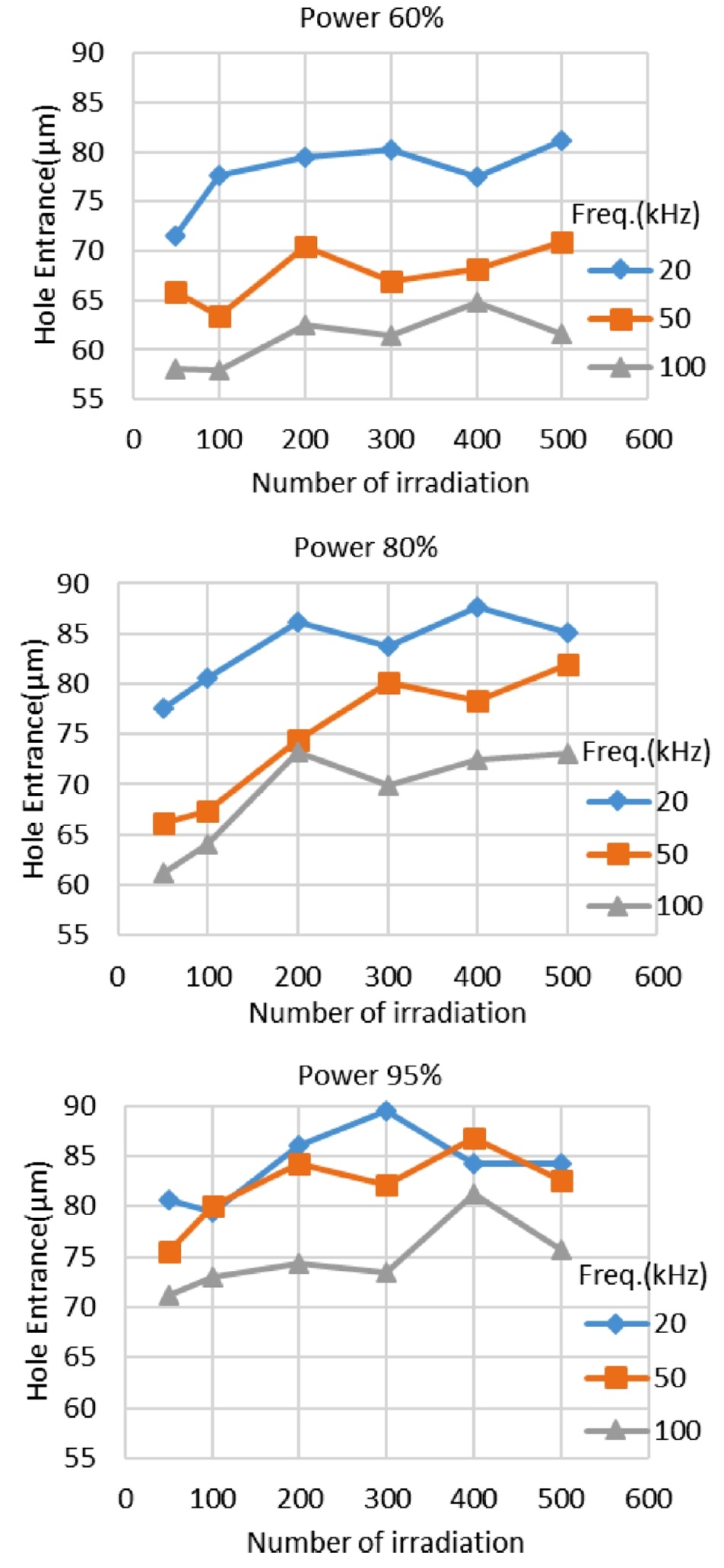
Fig. 7은
Table 4를 그래프로 나타낸 것으로, 출력 60, 80, 95%인 경우에 반복조사횟수에 따른 구멍크기(입구)를 나타낸다. 반복조사횟수가 증가하면 구멍크기가 증가하는 경향을 보인다. 또한 주파수가 커지면 구멍 크기는 작아지는 것을 알 수 있다. 3개 그래프의 같은 주파수 그래프끼리 비교해보면 출력이 증가하면 구멍크기가 커지는 것을 알 수 있다. 예를 들어, 주파수 20 kHz 그래프를 살펴보면, 출력 60%인 경우보다 출력 80%인 경우의 그래프가 더 위에 있으므로 증가함을 알 수 있다.
Fig. 7Hole entrance variation according to number of irradiation

5. 미세 구멍열(Micro Hole Array) 가공
5.1 구멍간격의 영향
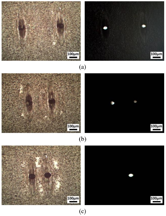
Fig. 8은 연속적인 구멍가공 시 구멍간격에 따른 결과를 보여준다. 레이저 조건은 출력 80%, 주파수 20 kHz, 반복조사횟수 300회이고, 시편은 평직직물 CFRP이다. 탄소섬유 방향에 따른 영향을 보기 위해서 탄소섬유의 방향과 구멍가공방향을 일치시켰다. 즉, 탄소섬유방향이 가로인 위치에 구멍 2개를 가로방향으로 가공하였다. 왼쪽구멍을 가공완료한 후 오른쪽 구멍을 가공하였다. 구멍간격이 0.5 mm인 경우에는 2개의 구멍이 성공적으로 가공되었다(
Fig. 8(a)). 간격이 0.3, 0.2 mm인 경우에는 투과조명을 사용하여 관찰하였을 때 첫번째 구멍이 막힌 것을 볼 수 있다(
Figs. 8(b),
8(c)). 구멍간격이 가까운 경우에는 두 번째 구멍 가공 시 첫번째 구멍 주변까지 열이 전달되어 레진이 녹아 첫번째 구멍을 막는 것으로 판단된다. 따라서 연속적인 구멍 가공 시, 구멍간격을 0.5 mm 이상으로 유지하는 것이 적절하다.
Fig. 8Drilling results according to distance between two holes: (a) 0.5 mm, (b) 0.3 mm, and (c) 0.2 mm (Fiber direction: horizontal, drilling direction: horizontal) (Laser: Power 80%, Freq. 20 kHz, No. of irradiation 300)
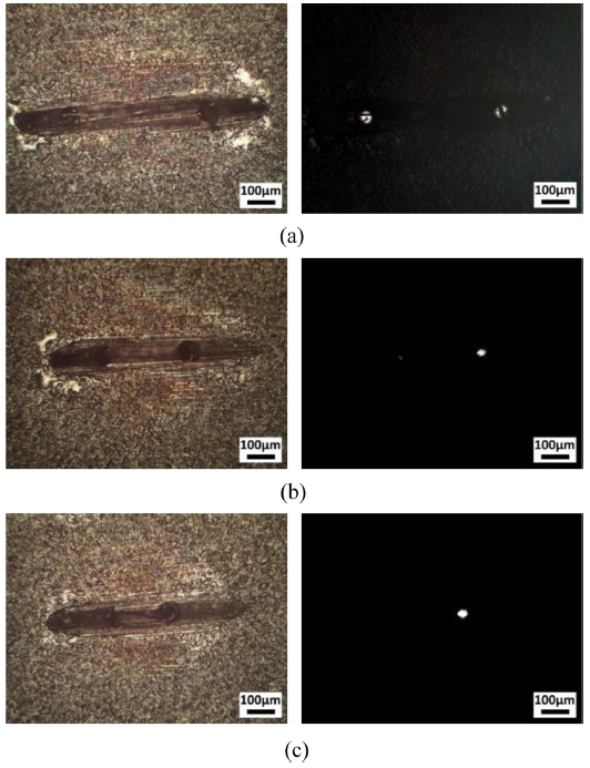
Fig. 9는 탄소섬유의 방향과 구멍가공방향이 수직이 되도록 하였고, 다른 조건은 동일하다. 즉, 탄소섬유방향은 세로이고, 구멍가공방향은 가로이다. 이 경우에는 간격이 0.3 mm 이상인 경우에 성공적으로 2개의 구멍이 가공되었고, 간격이 0.2 mm인 경우에 첫번째 구멍이 막힌 것을 볼 수 있다. 구멍가공방향과 탄소섬유방향이 수직인 경우에 구멍간격을 0.3 mm 이상으로 유지하는 것이 적절하다. 탄소섬유방향과 구멍가공방향이 같은 경우보다 수직인 경우가 구멍간격을 더 작게 할 수 있다. 이것은 탄소섬유방향으로 열전달이 더 잘되기 때문에 탄소섬유방향과 구멍가공방향이 같은 경우에 더 먼 간격에서도 열영향을 받아 레진이 녹아서 이전 구멍을 막기 때문으로 판단된다.
Fig. 9Drilling results according to distance between two holes: (a) 0.5 mm, (b) 0.3 mm, and (c) 0.2 mm (Fiber direction: vertical, drilling direction: horizontal) (Laser: Power 80%, Freq. 20 kHz, No. of irradiation 300)

5.2 레이저 스캔방법을 이용한 미세 구멍열(Micro Hole Array) 가공방법
구멍간격이 작은 연속적인 구멍가공을 위해서 레이저 스캔방법을 고안하였다.
Fig. 10은 주파수와 스캔속도에 따른 레이저 스팟을 보여준다. 일반적인 직선가공에서는 레이저 스팟이 중첩되며 가공이 이루어진다(
Fig. 10(a)). 만약 스캔속도가 빠르거나 주파수가 낮게 되면, 레이저 스팟 간격이 벌어지는데 이것을 연속적인 구멍가공에 활용할 수 있다(
Fig. 10(b)).
Fig. 10Laser spot distance variation according to scan speed and frequency: (a) for conventional cutting, (b) for micro hole array
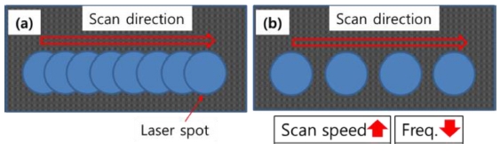
Fig. 11은 일반적인 연속구멍가공과 레이저 스캔방법을 비교하여 나타내었다.
Fig. 11(a)와 같이, 일반적으로는 한 구멍에 설정된 횟수만큼 레이저를 반복조사하여 구멍가공완료 후에 다음 구멍을 가공한다. 반면
Fig. 11(b)와 같이, 레이저 스캔방법은 설정된 길이만큼 스캔을 반복한다. 레이저 펄스에 번호를 붙여서 표현한다면 일반적인 구멍가공에서는 펄스 1,2,3,… 순서로 첫 번째 구멍에 계속 조사된다. 레이저 스캔방법에서는 첫번째 스캔으로 펄스 1,2,3,…,n이 각 구멍에 한번씩 조사된 후, 두번째 스캔에서 펄스 n+1,n+2,…,2n이 각 구멍에 순서대로 조사된다. 첫번째 구멍에서 살펴보면, 펄스1 조사 후 펄스 n+1이 조사된다. 즉, 펄스와 다음펄스 사이에 일정시간간격이 존재한다. 이 시간 간격으로 인해 열이 응집되어 넓은 열영향층이 형성되는 것을 방지해준다. 따라서 일반적인 구멍가공방법보다 구멍간격을 작게 할 수 있다.
Fig. 11(a) Conventional hole array machining method and (b) Hole array machining using laser scan method
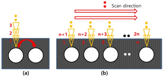
Fig. 12(a)는 스캔속도에 따른 구멍간격(Hole Spacing)의 변화를 나타낸다. 레이저 조건은 출력 95%, 주파수 20 kHz, 반복스캔횟수 100회이다. 시편은 일방향 CFRP를 사용하였다. 레이저 스캔방향은 탄소섬유방향과 수직이다. 스캔속도에 따라 선형적으로 구멍간격이 증가함을 볼 수 있다. 구멍간격은 최대 약 210 μm로 일반연속구멍가공법보다 구멍간격을 더 작게 가공할 수 있다.
Figs. 12(b)와
12(c)는 스캔속도 1500, 2000 mm/s인 경우의 1개 라인을 스캔한 구멍열 가공결과이다. 스캔속도 1500 mm/s의 경우는 구멍간격이 103.6 μm이고, 스캔속도 2000 mm/s인 경우에는 구멍간격이 133.98 μm이다. 구멍간격이 매우 작은데도 불구하고, 구멍 주변의 열영향층도 작고 성공적으로 관통되었음을 알 수 있다.
Fig. 12(a) Hole spacing according to scan speed, (b) single line hole array at 1500 mm/s, and (c) single line hole array at 2000 mm/s (Laser: Power 95%, Freq. 20 kHz, No. of scan 100) (Fiber direction: Vertical, Scan direction: Horizontal)

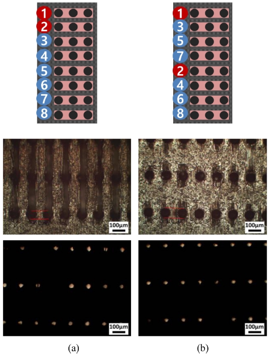
Fig. 13은 레이저 스캔을 세로방향 등간격으로 반복하여 미세 구멍열을 가공할 때 스캔순서에 따른 영향을 나타낸다. 세로방향으로 0.3 mm 간격으로 8개 라인을 스캔하였다. 탄소섬유방향은 세로이고 스캔방향은 수평이다. 레이저 조건은 출력 95%, 주파수 20 kHz, 스캔속도 2000 mm/s, 반복스캔횟수 100회이다.
Fig. 13(a)와 같이 위에서 아래로 순서대로 8개 라인을 스캔하면 두번째 라인을 스캔할 때 첫번째 라인의 구멍이 열영향을 받아 구멍입구주변이 섬유방향으로 손상되는 것을 볼 수 있다. 다만 관통에는 영향을 주지 않았다.
Fig. 13(b)와 같이 가공순서를 바꾸게 되면 첫번째 라인 가공 후에 멀리 떨어져서 두번째 라인을 가공하게 되어 열영향을 억제할 수 있게 된다. 구멍입구 주변에 열영향이 많이 줄어듦을 볼 수 있다.
Fig. 13Micro hole array with scan line spacing of 0.3 mm according to different scan sequence (Laser: Power 95%, Freq. 20 kHz, Scan speed 2000 mm/s, No. of scan 100) (Fiber direction: Vertical, Scan direction: Horizontal)
6. 결론
본 논문에서는 1064 nm Ytterbium Nanosecond Pulsed Fiber Laser를 이용한 0.5 mm 두께의 CFRP의 미세가공특성에 대해 연구하였다. 미세 절단가공의 경우에 출력이 낮은 경우에는 낮은 주파수에서만 절단되었고, 출력이 올라갈수록 높은 주파수에서도 절단되었다. 단, 주파수가 100 kHz로 높은 경우에는 어떤 조건에서도 절단되지 않았다. 가공폭은 출력이 커지면 증가하고, 주파수와 스캔속도가 커지면 감소하였다. 한 점을 반복조사하는 미세 구멍가공의 경우에도 출력이 낮은 경우에는 낮은 주파수에서만 관통되었고, 출력이 올라가면 높은 주파수에서도 관통되었다. 주파수가 100 kHz인 경우에는 어떤 조건에서도 관통되지 않았다. 구멍크기는 출력과 반복조사횟수가 커지면 증가하고, 주파수가 커지면 감소하였다. 미세 구멍열을 가공하는 경우에 구멍간격이 작으면, 열에 의해 녹은 레진이 이전구멍을 막았다. 좁은 구멍간격으로 구멍열을 가공하기 위해 레이저 스캔방법을 고안하였다. 라인스캔시, 주파수를 낮게 스캔속도를 크게하면 레이저 스팟이 중첩되지 않아 미세 구멍열 가공으로 활용가능하다. 구멍간격은 수십 μm에서 최대 약 210 μm까지 조절이 가능하였다. 레이저 스캔방법으로 구멍간격이 작고 열에 의한 손상도 거의 없는 미세 구멍열을 성공적으로 가공하였다.
ACKNOWLEDGMENTS
본 연구는 2018년 동양미래대학교 교내 학술 연구과제의 지원과 정부(교육부)의 재원으로 한국연구재단의 기초연구사업 지원으로 수행되었음(NRF-2017R1D1A1B03032887).
REFERENCES
- 1.
Roberts, T., “Rapid Growth Forecast for Carbon Fibre Market,” Reinforced Plastics, Vol. 51, No. 2, pp. 10-13, 2007.
10.1016/S0034-3617(07)70051-6
- 2.
Gang, M. G., Kim, G., Shin, K., Jeong, A., Kim, H. Y., et al., “Mechanical Cutting Process Trends for Difficult-to-Cut Materials : A Review,” Journal of the Korean Society for Precision Engineering, Vol. 35, No. 3, pp. 253-267, 2018.
10.7736/KSPE.2018.35.3.253
- 3.
Che, D., Saxena, I., Han, P., Guo, P., and Ehmann, K. F., “Machining of Carbon Fiber Reinforced Plastics/Polymers: A Literature Review,” Journal of Manufacturing Science and Engineering, Vol. 136, No. 3, Paper No. 034001, 2014.
10.1115/1.4026526
- 4.
Kim, H.-Y., Kim, T.-G., Lee, S.-W., Yoon, H.-S., Kyung, D.-S., et al., “Development of Manufacturing System Package for CFRP Machining,” Journal of the Korean Society for Precision Engineering, Vol. 33, No. 6, pp. 431-438, 2016.
10.7736/KSPE.2016.33.6.431
- 5.
Teicher, U., Müller, S., Münzner, J., and Nestler, A., “Micro-EDM of Carbon Fibre-Reinforced Plastics,” Procedia CIRP, Vol. 6, pp. 320-325, 2013.
10.1016/j.procir.2013.03.092
- 6.
Goeke, A. and Emmelmann, C., “Influence of Laser Cutting Parameters on CFRP Part Quality,” Physics Procedia, Vol. 5, pp. 253-258, 2010.
10.1016/j.phpro.2010.08.051
- 7.
Jaeschke, P., Stolberg, K., Bastick, S., Ziolkowski, E., Roehner, M., et al., “Cutting and Drilling of Carbon Fiber Reinforced Plastics (CFRP) by 70 w Short Pulse Nanosecond Laser,” Proc. of High-Power Laser Materials Processing: Lasers, Beam Delivery, Diagnostics, and Applications III, International Society for Optics and Photonics, Vol. 8963, Paper No. 89630S, 2014.
10.1117/12.2036086
- 8.
Wolynski, A., Herrmann, T., Mucha, P., Haloui, H., and L’huillier, J., “Laser Ablation of CFRP Using Picosecond Laser Pulses at Different Wavelengths from UV to IR,” Physics Procedia, Vol. 12, pp. 292-301, 2011.
10.1016/j.phpro.2011.03.136
- 9.
Kim, S., Kim, B. H., Shin, H. S., and Chu, C. N., “Hybrid Micromachining Using a Nanosecond Pulsed Laser and Micro EDM,” Journal of Micromechanics and Microengineering, Vol. 20, No. 1, Paper No. 015037, 2009.
10.1088/0960-1317/20/1/015037
Biography
- Do Kwan Chung
Associate Professor in the School of Robot and Automation Engineering, Dongyang Mirae University. His research interest is micro machining.
- Jin Sung Park
Undergraduate Student in the School of Robot and Automation Engineering, Dongyang Mirae University. Currently, Researcher in the Analysis Team, APRO Inc. His research interest is micro machining.
- Ki Hun Kim
Undergraduate Student in the School of Robot and Automation Engineering, Dongyang Mirae University. His research interest is micro machining.