ABSTRACT
Freeform surfaces are widely used in various industries. However, they require much time to be machined because of complicated geometry. To increase machining productivity, partitioning methods for freeform surface have been proposed by several previous studies regarding selection of cutting tools and tool-path. This paper proposes a new partitioning method based on Gaussian and mean curvatures to define boundaries of local patches using Freeman algorithm. Simulation results with a B-Spline surface show that the proposed method combined with cutting tool selection strategies can reduce machining time and surface roughness when compared with the non-partitioned method.
-
KEYWORDS: Tool radius selection, Free form surface, Partitioning surface, Freeman algorithm
NOMENCLATURE
Equation of freeform surfaces
Coefficients of the first fundamental forms
Coefficients of the second fundamental forms
Saddle surface, concave surface and convex surface
Principle curvatures of saddle surface
Principle curvatures of concave surface
Principle curvatures of convex surface
Tool diameter of respectively patch
1. Introduction
Nowadays, freeform surfaces are more and more used in various fields of the industry as the automobile, hydrodynamics, air-dynamics or gas-dynamics applications, mold and die manufacture, consumer electronic products, optical and medical parts, and so on. 3-axes or 5-axes CNC milling machines tools can be used to machine freeform surfaces. Using 5-axes CNC milling machines is more effective than 3-axes CNC milling machines because of its flexibility. In this case, the cutting tool can approach the machining surface in various directions to create the surfaces without changing the work-piece setting. So, it is easy to adjust the scallop height from two successive tool-paths. However, there are some disadvantages from using 5-axes CNC milling machines in Vietnam as high cost, the difficulty of operation. Thus, 3-axes CNC milling machines are still important in manufacturing. But, the approaching direction of the cutting tools is not adjustable in this case. So, the tools must be selected with smaller diameters, which are appropriated with the curvature of concave area to avoid concave-gouge as well as required geometrical accuracy. Then, the time of machining will be increased, and the productivity will be reduced. There are many studies to improve productivity and quality of the machining freeform surfaces. My Chu A. et al.
1 introduced a method of machining freeform surfaces by an orientation of cutting tool according to a normal vector field. The research proposed a direction to approach the surface to ensure required scallop height. However, this method is only appropriate to 5-axes CNC milling. Radzevich
2 developed a method of feasible approaching to the surface. It means that the cutting tools approach the surface from different directions in the condition of no gouge. This method is also applicable to 5-axes CNC milling. Castillo et al.
3 proposed a method of partitioning freeform surfaces into patches so that each patch can be machined effectively. The authors used C-mean to partition the surface. Besides that, the Voronoi diagram was used to define the boundary of each patch. Several researchers studied on NURBS path generation such as the method of interpolation of tool path along NURBS surface based on open source,
4 the method of tool path generation for finishing when machining free surface on a 3-axis CNC machine.
5 Recently, Xu. J et al
6 proposed the method for spiral tool path generation based on mesh surface which was guided by radial curves and applied for high-speed machining. To create tool paths for pattern sculpting on the 3D surface,
7 the authors used 2D pictures to convert into separate data points then generate 3D tool path by fuzzy mapping image processing. However, there are no researches on partitioning free-form surface and then using the partition surface to select reasonable tool radius and tool paths.
A solution of partitioning freeform surfaces based on Gaussian and mean curvature has been studied and presented in the paper. The surface is first partitioned into local patches and boundaries of local patches are then defined by Freeman algorithm. From that, tools and tool-paths are selected to appropriate with each patch for machining whole freeform surface. This is potential methods to reduce machining time and increase productivity and geometrical accuracy of the finishing machined surface.
2. Proposal Method
The general equation of the surface in Cartesian coordinate system
8,9 as
Eq. (1).
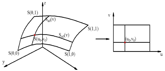
The equation can be used to represent basic surfaces as sphere, cylinder, cone and so on. Parametrical equations with two parameters
u,
v are used to represent freeform surfaces by mapping from R
3 space to R
2 space as show in
Fig. 1 and expressed in
Eq. (2).
Fig. 1 3D points S(x0, y0, z0) mapping to 2D points S(u0, v0)
In the parameters
u and
v space, freeform surface
S(
u,
v) described by
Eqs. (3) and
(4).
where S(u, v) - equation of freeform surfaces; {Pi,j} - bidirectional control points; wi,j - weights; Ni,p(u), Nj,q(v) - the non-rational B-spline basis functions defined on the knot vectors; U, V - knot vectors as expressed:
2.1 Surface Partition and Radius’s Ball-End-Tool Calculation
The aim of a freeform surface fraction is appropriately selecting cutting tools, tool-paths for each local patch. It will result in decreasing machining time but maintaining machining accuracy. The partitioning of the freeform surface is carried out based on the curvature of the surface at any point. Sets of points with the same curvature property are grouped. The curvature properties included Gaussian curvature (
K) and mean curvature (
H),
9 which can be defined by
Eq. (5).
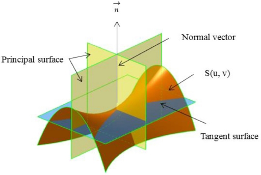
where
K1,P,
K2,P - principal curvatures, defined on principal planes (
Fig. 2); E, F, G and L, N, M are the coefficients of the first and second fundamental forms, respectively, which was expressed as:
Fig. 2Principal curvatures

According to Gaussian curvature (
K) and mean curvature (
H), a freeform surfaces
S(
u,
v) can be partitioned into 10 local patches (
Table 1). Each patch has distinct property on Gaussian curvature
K and means curvature
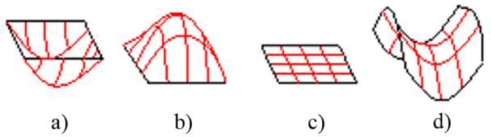
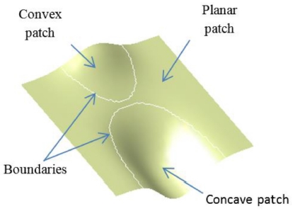
H. In order to simplify, there isn't necessary to partition the surface into 10 local patches for machining. The surface could be partition into 4 local patches, which is popular and vital for deciding to select cutting tool and tool-path. They are planar patch (
H=
K=0), convex patch (
H>0;
K≤0), concave patch (
H<0
K<0) and saddle-like patch (
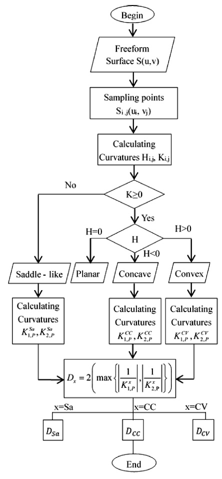
Fig. 3). To partition a surface, Gaussian curvature (
K) and mean curvature (
H) are firstly calculated. Based on values of
H and
K, all of the points with the same properties of the curvatures will be then grouped into a set of points. The set represents for a local surface patch. The algorithm for the partition is shown in
Fig. 4.
Table 1Partitioning free form surface based on K and H
Table 1
|
No. |
Gaussian
curvature |
Mean
curvature |
Local patch |
|
1 |
K<0 |
H<0 |
Concave elliptic |
|
2 |
|
H=K<0 |
Concave umbilic |
|
3 |
|
H>0 |
Convex elliptic |
|
4 |
K=0 |
H<0 |
Concave parabolic |
|
5 |
|
H=K=0 |
Parabolical umbilic |
|
6 |
|
H>0 |
Convex parabolic |
|
7 |
K>0 |
H<0 |
Quasi-concave saddle-like |
|
8 |
|
H=0 |
Minimal saddle-like |
|
9 |
|
H>0 |
Quasi-convex saddle-like |
|
10 |
|
H=K>0 |
Convex umbilic |
Fig. 3Four popular local surface patch: (a) Concave patch, (b) Convex patch, (c) Planar patch, and (d) Saddle patch

Fig. 4The algorithm on calculating of tool’s radius
2.2 Boundaries Definition of Local Surface
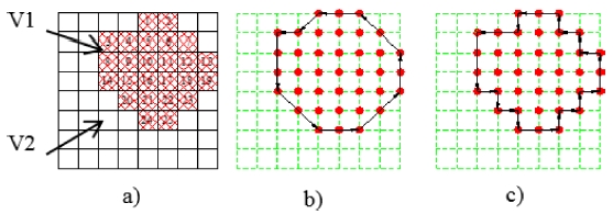
The partitioned surface with four patches could not be readily used for machining because the boundaries of the cutting areas haven’t been defined. An algorithm for defining the boundary based on Freeman algorithm has been proposed. There is a planar patch with two areas V1 and V2 (
Fig. 5(a)). Each point is described as a square. In the area V1, the points are numbered from 1 to 25. We can see that each point has maximum of 8 neighboring points including points on diagonal, and 4 neighboring points excluding points on diagonal. Two kinds of defining neighboring points in 2D space are shown in
Fig. 6.
Fig. 5The points of the planar area and two cases of creating boundary

Fig. 6The direction of connection neighboring points: (a) 4 links of points and (b) 8 links of points
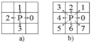
For example, as shown in
Fig. 5, there are 8 neighboring points around point 16 as 10, 11, 17, 22, 21, 20, 15, and 9 under 8 neighboring points condition and there are 4 points 10, 17, 21, 15 under 4 neighboring points condition. So, according to the condition of 4 neighboring points, if each point has 4 neighboring points then it is inside the boundary and if it has less than 4 neighboring points then it is on the boundary. Similarly, the condition of 8 neighboring points can be applied. The points along the boundary can be defined and connected in sequence to create the boundary. In this example, by applying the 4 neighboring points condition, the boundary of area V1 can be defined by connecting points 1 → 4 → 3 → 8 → 14 → 20 → 24 → 25 → 23 → 19 → 13 → 7 → 2 → 1, respectively (
Fig. 5(b)). Similarly, by applying the 8 neighboring points condition, the boundary V1 can be defined by connecting points 1 → 5 → 4 → 3 → 8 → 14 → 15 → 20 → 21 → 24 → 25 → 22 → 23 → 18 → 19 → 13 → 12 → 7 → 6 → 2 → 1, respectively (
Fig. 5(c)). The accuracy of the boundary of the latter is higher with the expense of calculating.
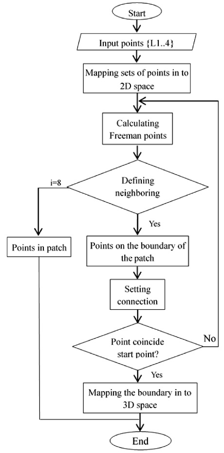
The research has applied Freeman algorithm with 8 links of point, that will result in higher accuracy of the boundary. The algorithm on defining the boundary includes 4 steps as following:
Step 1: Mapping the set of 3D points, which has been partitioned into 2D space with two-dimensional coordinates u, v. We have the sets of points of four local patches, are named in term as: L1 (The saddle-like area), L2 (the planar area), L3 (convex area), L4 (concave area). The sets of points {L1}, {L2}, {L3}, and {L4} are stored in matrixes n x2 ( n corresponding to number of points, 2 corresponding to coordinates of points). The matrix has a form as expression (5) with two coordinates u, v for each point.
Step 2: Calculating Freeman points and defining a number of neighboring points i. If i<8 then the considered point on the boundary and the point is connected. Such a process is repeated until the considered point coincides with the start point of the boundary. So, at last, we have the boundary of the local patch on 2D space.
Step 3: Inversely mapping the boundary into 3D space, we have the boundary of the local patch. The algorithm is described in details on the diagram in
Fig. 7.
Fig. 7An algorithm of creating the boundary of the local freeform patch.
Based on two proposed algorithms, a program has been written by Matlab 2014a. This is an effective tool for partitioning a freeform surface. After partitioning a freeform surface and defining boundaries of the local surface patches, we can select cutting tools and tool-paths that appropriate with each local patch. Then we can machine each patch with the selected tool and tool-path. That will be more effective than machining whole the surface with one tool and one strategy of the tool-path. The effectiveness of the proposed solution is verified by a case of study, that is presented in the next part.
2.3. A Case of Study
In order to verify the proposed method, a simple freeform surface is selected to test. This is a B-spline surface with control points net 5 × 5, weight at every control point w = 1, knot vector [0 0 0 1/3 2/3 1 1 1] on two parameter directions (
Table 2). After partitioning the surface and defining boundaries by a program written by MATLAB with the algorithm in
Figs. 4 and
7, we have three patches: convex patch, concave patch, planar patch and two boundaries (
Fig. 8). Using Catia V5R20 to simulate the machining the B-spline surface with two samples. The B-spline surfaces are non-partitioned in Sample 1 and partitioned in Sample 2, respectively. The simulation is carried out as the following procedures:
Table 2The net of control points of the B-spline
Table 2
|
P00(-50,-50,0) |
P12(-50,-25,0) |
P13(-50,0,0) |
P14(-50,25,0) |
P15(-50,50,0) |
|
P21(-25,-50,0) |
P22(-25,-25,0) |
P23(-25,0,0) |
P24(-25,25,0) |
P25(-25,50,0) |
|
P31(0,-50,-20) |
P32(0,-25,-20 |
P33(0,0,-15) |
P34(0,25,0) |
P35(0,50,20) |
|
P41(25,-50,0) |
P42(25,-25,0) |
P43(25,0, 0) |
P44(25,25,0) |
P45(25,50,0) |
|
P51(50,-50,0) |
P52(50,-25,0) |
P53(50,0,10) |
P54(50,25,0) |
P55(50,50,0) |
Fig. 8Local patches and boundaries
Step 1: Both of two samples are roughly machined with the same cutting tool (D1 = 10 mm), feed-rate = 400 mm/min and scallop height of 0.1 mm, the same type of tool-path and the same cutting regime. The rough milling leaves an allowance of 0.1 mm which will be removed in finish milling.
Step 2: Finishing the sample 1 by a ball mill with diameter D2 = 3 mm to avoid gouge at the concave area, zig-zag tool-path, feed-rate = 1000mm/min and scallop height of 0.05 mm (
Fig. 9(a)).
Fig. 9Tool path procedures of (a) sample 1with 3 mm tool diameter and (b) sample 2 with two tools (stage 1-8 mm tool diameter for the convex surface; stage 2-3 mm tool diameter for the concave surface and stage 3 - the final simulation result
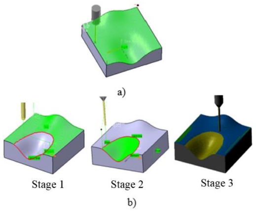
Step 3: Finishing the sample 2 (
Fig. 9(b)). The surface is partitioned into three patches (concave, convex and planar). For concave patch, the cutter, tool-path and cutting regime are the same as the sample 1. For convex patch and planar patch, the cutter with diameter D2 = 8 mm is selected, because the gouge doesn’t occur in these cases, other parameters have remained the same in step 2.
3. Results and Discussion
As shown in
Table 3, it is noticed that the quality of the machined surfaces of the two samples is similar by selecting the same scallop height. And programs for roughing of two samples are the same, too. But there is a difference of programs for finishing samples. The simulation results showed that for Sample 1 (non-partitioned surface): a total of machining time is 2h06m40s, while for Sample 2 (partitioned surface): a total of machining time is 1h42m32s. It means that the proposed method can reduce machining time. Also, there are the decreasing of other output data such as tool path length and cutting length (
Table 3).
Table 3 Results of simulation
Table 3
|
No. |
Specification |
Sample 1 |
Sample 2 |
Sample 3 |
|
1 |
Machining time |
2h06m40s |
1h42m32s |
1h40m20s |
|
2 |
Cutting time |
2h05m45s |
1h41m25s |
1h39m15s |
|
3 |
Tool change time (s) |
20s |
30s |
30s |
|
4 |
Tool path length (mm) |
231410.219 |
207724.147 |
203850.330 |
|
5 |
Cutting length (mm) |
227870.088 |
204098.335 |
200250.225 |
|
Roughing’s Time = 1h9m20s |
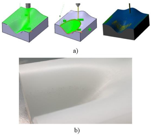
To prove the quality of product, the experiment process has been performed for the sample 2 according to proposed method by 3-axis Hamai CNC milling machine 3 VA (Working space, XxYxZ = 800 × 450 × 450; Table size 1300 × 520; Maximum load 800 kg; Spindle speed: 6000 v / minute; cutting tool type: BT40; Number of cutting tool: 24) as shown in
Fig. 10(a). The experimental result is depicted in
Figs. 10(b) and
10(c).
Fig. 10 Experimental machining process for sample 2 on 3-axes CNC machine (a), Experimental result of sample 2 (b) and roughness curves occurrence after machining (c)
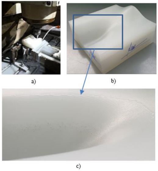
As shown in
Fig. 10(c), there is roughness curves occurring at the boundary of the concave patch and planar patch. This is due to the selection of different tool radius in Step 3. The tool-paths are automatically generated by Catia V5R20 then the calculation based on the boundaries points for cutting location data will lead to underestimating the accuracy of product at this zone. To overcome this error, this study also proposed tool selection steps for finishing machining the sample 3 as following: The surface is partitioned similar sample 2, means that the surface is partitioned into three patches (convex, concave and planar). For convex and planar patches, the cutter ball-end-mill with diameter D2 = 8 mm is selected and machining all surface area with scallop height similar to machining sample 2 (0,05 mm). For concave patch, the cutter is ball-end-mill with diameter D3 = 3 mm is selected as shown in
Fig. 11(a). The output data of machining simulation such as machining time, cutting length and tool path length are also presented in
Table 3. The results showed that more reduction of machining time, tool-path length and cutting length. The corresponding experimental result of sample 3 is also presented in
Fig. 11(b) with good improved geometrical accuracy of smooth surface. The machining simulation output data and experimental result of sample 3 show that the proposed method is initially effective when compared with the machining freeform surface by using the traditional method.
Fig. 11 The tool path generation for sample 3 (a) and corresponding experiment without roughness at the boundary of the concave patch and planar patch (b)

4. Conclusions
This study proposed a method of partitioning free form surfaces based on Gaussian and mean curvatures and defining boundaries of the local patches by Freeman algorithm. The method is confirmed by corresponding experiments with a B- spline surface. Through the simulation and experiment of machining the partitioned B- spline surface, the effectiveness of the method is clearly expressed.
The results are the foundation for optimal selection of tools and tool-path in machining freeform surfaces on 3-axes CNC milling machines to reduce machining time, while ensuring the surface quality. The results can be applied for future studies on 5-axes CNC milling. However, it requires more simulations as well as machining experiments to verify the method.
ACKNOWLEDGMENTS
This paper was presented at PRESM 2019
REFERENCES
- 1.
My, C. A., Bohez, E. L., Makhanov, S. S., Munlinb, M., Phien, H. N., et al., “On 5-axis Freeform Surface Machining Optimization: Vector Field Clustering Approach,” International Journal of CAD/CAM, Vol. 5, No. 1, pp. 1-14, 2009.
- 2.
Radzevich, S. P., “Geometry Kinematic Geometry Machining,” CRC Press, 1st Ed., 2007.
10.1201/9781420063417
- 3.
Del Castillo, E., Colosimo, B. M., and Tajbakhsh, S. D., “Geodesic Gaussian Processes for the Parametric Reconstruction of a Free-Form Surface,” Technometrics, Vol. 57, No. 1, pp. 87-99, 2015.
10.1080/00401706.2013.879075
- 4.
Valvo, E. L. O., Drago, S. I., Chimica, I. M., and Scienze, V., “An Efficient NURBS Path Generator for a Open Source CNC,” Recent Advances in Mechanical Engineering, pp. 173-180, 2014.
- 5.
Wright, P. K., Dornfeld, D. A., Sundararajan, V., and Mishra, D., “Tool Path Generation for Finish Machining of Freeform Surfaces in the Cybercut Process Planning Pipeline,” Transactions of the North American Manufacturing Research Institute of SME, Vol. 32, pp. 159-166, 2004.
- 6.
Xu, J., Ji, Y., Sun, Y., and Lee, Y.-S., “Spiral Tool Path Generation Method on Mesh Surfaces Guided by Radial Curves,” Journal of Manufacturing Science and Engineering, Vol. 140, No. 7, Paper No. 071016, 2018.
10.1115/1.4039918
- 7.
Xu, J., Zhang, X., Wang, S., and Wu, J., “Tool Path Generation for Pattern Sculpting on Free-Form Surfaces,” The International Journal of Advanced Manufacturing Technology, Vol. 67, Nos. 9-12, pp. 2469-2476, 2013.
10.1007/s00170-012-4664-4
- 8.
Del Castillo, E., Colosimo, B. M., and Tajbakhsh, S. D., “Geodesic Gaussian Processes for the Parametric Reconstruction of a Free-Form Surface,” Technometrics, Vol. 57, No. 1, pp. 87-99, 2015.
10.1080/00401706.2013.879075
- 9.
Castillo, E. B. M., Colosimo, S. D., Tajbakhsh, B. M., and Astillo, E. C., “Geodesic Gaussian Processes for the Parametric Reconstruction of a Free-Form Surface Geodesic Gaussian Processes for the Parametric Reconstruction of a Free-Form Surface,” Vol. 1706, No. 1, pp. 1-25, 2016.
Biography
- Bui Ngoc Tuyen
Associate Professor in the School of Mechanical Engineering, Hanoi University of Science and Technology, Vietnam. His research interests are CAD/CAM/CAE and Machining process.
- Hoang Van Quy
Master in the School of Mechanical Engineering, Haiphong University of Vietnam. His research interests are CAD/CAM/CAE and Machining process.
- Duc-Toan Nguyen
Associate Professor in the School of Mechanical Engineering, Hanoi University of Science and Technology, Vietnam. His research interests are Plasticity, Machining Process, CAD/CAM/CAE.