ABSTRACT
In this paper, when the finishing process is performed on the additive by FDM type, the optimal parameter set of the additive-finishing design parameters to improve the surface quality and the verification of the finishing effect are described. Additive design parameters such as nozzle diameter and layer height and finishing design parameters such as depth of cut and feed rate have a significant influence on the printing time and surface roughness of the sculpture. So, we define the major additive-finishing design parameters expected to affect the results. So, we define the major additive-finishing design variables that expected to affect the experimental results. And to confirm how much they affect the results with the minimum number of experiments, the sensitivity analysis of the design parameters was performed through the level average analysis of the Taguchi method. As a result, compared to the surface roughness and additive time when only high-quality sculpture was performed, and it was confirmed that the printing time improved up to 70% and the surface roughness improved up to 87% for the additive-finishing sculpture performed with the optimal combination of design parameters.
-
KEYWORDS: Additive manufacturing, Fused decomposition modeling, Surface roughness, Finishing process
-
KEYWORDS: 적층 제조, 용착 조형 공정, 표면 조도, 정삭 공정
NOMENCLATURE
Center-Line Average Roughness
1. 서론
적층 제조(Additive Manufacturing, AM) 산업은 다보스 포럼 이후 제조 산업의 핵심요소 중 하나로써 빠르게 성장해왔으며, 코로나19 이후 스마트 제조 공정에 대한 수요의 확대로 인해 연평균 18%씩 성장하고 있는 추세이다.
1-3 적층 제조 장치는 출력물의 제작 방식에 따라 고체 재료에 열을 가하여 녹인 뒤 노즐로 적층 하여 쌓아 올리는 방식인 용착 조형 공정(Fused Deposition Modeling, FDM) 방식, 광경화성 액상 수지를 레이저로 응고시키는 방식인 광조형 공정(Stereolithography Apparatus, SLA) 방식 및 다양한 분말 형태의 재료 등을 쌓아가면서 레이저나 액체 접착제 등으로 용합시키는 방식인 선택 레이저 소결법(Selective Laser Sintering, SLS) 방식 등으로 구분된다. 그 중에서 FDM 방식은 Polylactic Acid (PLA)와 Acrylonitrile Butadiene Styrene Copolymer (ABS)와 같은 엔지니어링 플라스틱을 고온으로 가열하여 적층하는 방식으로 원가의 저렴함과 적층 기술의 단순함으로 인해 다른 방식에 비해 비용 및 생산성 측면에서 우수한 성능을 보인다.
4
그러나
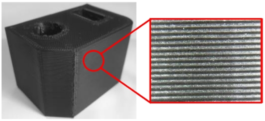
Fig. 1에서도 볼 수 있듯, FDM 방식은 고열의 노즐을 통해 재료를 한 층씩 적층하는 방식의 특성상 출력물의 품질을 결정하는 표면 조도(Surface Roughness)와 조형 시간이 서로 상충관계(Trade-Off)에 놓여있기 때문에, 소량의 시작품 제작 외 다른 산업적 분야로의 활용이 매우 제한적인 상황이다. 이러한 문제를 해결하기 위해 조형물의 표면 조도 향상을 위한 다양한 연구들이 수행되어 왔다.
5-11 Saad et al.
11은 FDM 출력물의 표면 거칠기를 최소화하는 최적의 적층 설계변수 조합의 탐색을 실험계획법을 통해 수행하였다. 그러나 이는 FDM 방식 자체의 한계를 보완한 것이 아니기 때문에 여전히 표면 조도와 조형시간 사이의 상충관계 문제는 남아있다.
Fig. 1 Surface of a sculpture printed by FDM method

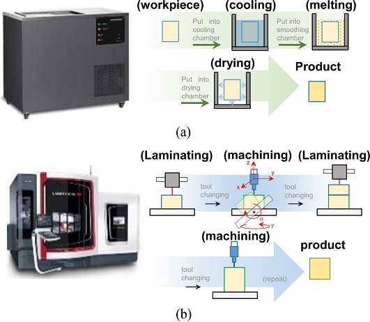
Fig. 2(a)에는 엔지니어링 플라스틱으로 가공된 조형물에 화학 공정을 통해 표면 조도를 향상시키는 과정이 나와있다. 미국 Stratasys사의 Smoothing Station은 이 방법을 통해 조형물의 표면 조도를 향상시킨다. 그러나 화학 처리를 통한 후처리 방법의 특성상 조형물의 설계 당시에 의도하지 않았던 라운딩 현상이 발생하고, 화학 처리를 위한 추가적인 공간과 시간이 필요하게 된다.
Fig. 2(b)에는 DMG-MORI사의 Lasertec으로 대표되는 기계적 후처리 가공을 통한 조형물의 표면 조도 향상 과정이 나와 있다. 절삭 공정은 화학적 공정에 비해 설계 정밀도가 향상되는 반면에 장비가 차지하는 부피 대비 작업 영역 부피가 작아 작업 영역 효율이 떨어지고, 오로지 금속 소재에 대해서만 조형물의 적층-정삭이 가능하다는 단점이 존재한다.
Fig. 2 Post-processing of FDM 3D sculpture: (a) Chemical treatment, and (b) Finishing cutting

따라서 본 논문에서는 FDM 적층 제조 장치를 이용한 PLA 소재 출력물에 정삭 공정을 통해 후처리를 수행함에 따라 적층 및 정삭 공정 설계변수 간의 상관관계에 대한 연구가 진행된다. 최적 설계변수 조합을 찾기 위한 시행착오를 줄이기 위하여 실험계획법인 다구치 방법(Taguchi Method)의 수준 평균분석법(Level Average Analysis)을 수행한다. 주요 적층-정삭 설계변수를 정의하고, 민감도 분석을 수행하여 각 설계변수들이 결과에 미치는 영향에 대해 분석하고 이를 최적화한다. 그 후 최적 설계 변수 조합에서의 적층-정삭 결과를 확인하여 향상도를 평가한다.
2. 문제 정의
Table 1에는 본 연구에서 대상으로 하는 적층-정삭 설계변수가 정의되어 있다. 2.1절에서는 적층 공정과 관련된 설계변수에 대해, 2.2절에서는 정삭 공정과 관련된 설계변수에 대해 기술하였으며, 개별적으로 분리된 적층 공정과 정삭 공정 사이의 특성상 서로 구분하였다.
Table 1 List of experimental variables
Table 1
Additive
parameter |
Tn
|
Nozzle temperature [oC] |
|
dn
|
Nozzle diameter [mm] |
|
h |
Layer height [%] |
|
vl
|
Speed of additive [mm/s] |
|
ρ |
Infill density [%] |
Finishing
parameter |
ldoc
|
Depth of cut [mm] |
|
ws
|
Spindle RPM [rpm] |
|
vfr
|
Feed rate [mm/s] |
2.1 적층 실험 설계변수 정의 및 선정
본 연구에서 사용한 FDM 3D 프린터는 Creality사의 Ender-5K 모델이다. 일반적으로 적층 제조 장치의 적층 출력을 위한 설계변수는, 상용 슬라이서(Slicer) 소프트웨어에서 자유롭게 변경이 가능하다. 그러나 해당 값들의 변동에 따라 적층 조건이 임의로 재설정되었을 때 프린터는 불안정한 출력을 하게 되어 조형물의 표면 조도 성능이 상당히 떨어지거나, 조형물이 형상 자체를 유지할 수 없게 될 수도 있다. 즉, 적층 제조를 수행하기 전 적층 설계변수들의 대한 이해와 올바른 조합의 선정이 선행되어야 출력물의 온전한 조형이 가능하다.
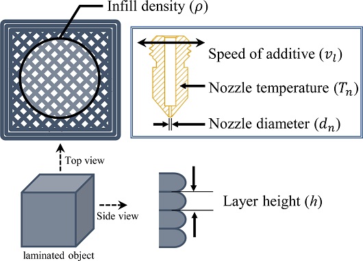
Fig. 3은 적층 설계변수에 대한 개념도로써, 조절 가능한 설계변수들 중 본 연구에서 적층 설계변수로 선정한 다섯 가지가 표시되어 있다. 먼저, 조형물의 쾌속 조형을 위해서는 필라멘트의 유량이 증가하여야 한다. 아래
식(1)로부터 유량을 늘리기 위해 조절해야 하는 설계변수는 d
n, h 및 v
l임을 알 수 있다.
Fig. 3Additive parameter schematic diagram
압력과 온도를 통해 필라멘트를 녹여 배출하는 실질적인 부품인 노즐에서 변경 가능한 설계변수는 Nozzle Diameter (d
n)로, 동일시간 대비 출력되는 면적을 설정하는 주요 설계변수다. 따라서 d
n의 값이 커질수록 더 쾌속 조형이 가능하다. 본 연구에서 정의하는 d
n의 Level은 1.0, 1.5, 2.0 mm 크기로 일반적으로 FDM 방식에서 일반적으로 쓰이는 크기인 0.4-0.8 mm보다 큰 값을 사용한다.
12,13
Layer Height (h)는 프린팅 평면의 Z축으로 이동하는 과정에서 한 Layer의 높이를 나타내는 설계변수로 재료의 안정적인 적층을 위해 Nozzle 직경의 10-40% 사이에서 설정한다. h가 작을수록 표면 조도는 향상되나 출력물의 층수 증가로 인한 Z축 방향의 출력 경로가 증가하게 되어 출력 시간은 증가하게 된다. 그러나 본 연구에서 사용하는 d
n은 상대적으로 큰 값을 가져, h가 높아지면 적층 유지가 불가능하다. 따라서 d
n을 낮추고, h를 높여 적층하는 것보다 d
n을 키우고 h를 줄이는 것이 쾌속 조형에 가까워지므로 본 실험에서는 h를 10, 20, 30%로 설정하였다.
14
적층 속도(Speed of Additive, v
l)는 조형물을 출력할 때 노즐의 속도를 의미한다.
식(1)에서도 알 수 있듯, 노즐 속도가 증가함에 따라 유량이 증가해 쾌속 조형이 가능하다. 따라서 v
l을 실험 설계변수로 설정하고 40, 60, 80 mm/s로 수준을 지정한다.
15
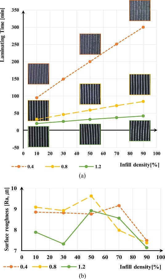
Infill Density (ρ)를 향상시키면 출력물의 기계적 성질(Mechanical Property)가 증가하지만 조형 시간 또한 증가하게 된다. 그러나 정삭 진행 시 조형물 자체의 떨림 및 진동이 최소화가 되어야 하기 때문에 ρ에 대해서는 구체적인 평가가 필요하다. 따라서, dn과 ρ를 설계변수로 테스트를 진행하여 ρ의 Level을 결정하였다.
실험에서의 h는 40%로, v
l는 80 mm/s로 하였으며, ρ만을 설계변수로써 10, 30, 50, 70, 90%의 값으로 변화시키며 출력 시간 및 정삭 후의 표면 조도값을 확인하였다. 그 결과
Figs. 4(a)와 같이 ρ에 따라 출력 시간이 증가하는 양상은 확인할 수 있었으나,
4(b)에서처럼 표면 조도에서는 밀도에 따라 변화하는 경향은 확인할 수 없었다. 이는 낮은 밀도 조건에서도 조형물이 온전한 정삭을 수행할 수 있는 기계적 성질을 가짐을 의미한다. 따라서, 본 연구에서는 본 실험에서는
ρ를 실험 설계변수로 설정하고 20, 40, 60%로 지정하여 실험을 진행한다.
Fig. 4(a) Additive time for infill density, and (b) Surface roughness for infill density

재료가 압출되기 전에 FDM의 가열 노즐 내부에서 유지되는 온도를 Printing Temperature (T
n)이라고 한다. 출력에 사용되는 재료의 점도에 영향을 미친다. T
n은 필라멘트 재료의 유동성을 증가 또는 감소시켜 차례로 제조되는 구성요소에 영향을 줄 수 있으므로 항상 유지되어야 한다. T
n는 필라멘트를 녹일 수 있는 값인 190
oC 이상의 온도가 반드시 보장되어야 한다. 따라서, Printing Temperature를 실험 설계변수로 설정하고, 2 수준의 200과 210
oC로 설정한다.
16-18
FDM 조형물의 표면 조도를 개선하기 위하여 밀링 머신을 이용하여 표면 정삭 과정을 진행한다. 본 장에서는 조정 가능한 정삭 설계변수들에 대하여 나열하고, 실험 설계변수 선정에 대하여 기술한다.
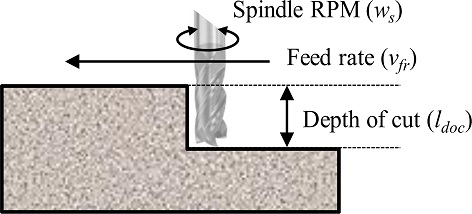
Fig. 5에 표현된 Depth of Cut (l
doc)은 정삭 진행 시 표면으로부터의 공구 삽입 깊이를 의미한다. 본 실험에서는 l
doc를 실험 설계변수로 설정한다. 적층 조형물의 측면부에 대한 정삭을 진행하므로, l
doc양은 d
n의 30, 50, 70%로 설정한다.
Fig. 5Finishing parameter schematic diagram

밀링 머신을 사용하여 조형물의 정삭 가공 시 조형물의 표면에 직접 닿는 엔드밀은 크게 두 종류로 구분된다. 먼저, 볼엔드밀로 정삭을 진행하였을 때 조형물의 표면에 엔드밀이 지나간 경로가 그대로 나타나는 등의 정삭 흔이 발생한다. 따라서 본 실험에서는 Flat 타입의 엔드밀을 사용한다. 더불어 Spindle RPM (vfr)과 Feed Rate (ws) 또한 실험 설계변수로 설정하고, 각각 520, 760, 990 rpm 및 10, 25, 40 mm/s로 지정한다.
3. 실험 및 분석
본 연구에서는 FDM 조형물의 출력 후 정삭에 따른 표면 품질의 향상도를 정량적으로 평가하기 위하여 표면 조도를 성능 지표로 선정한다. 단순히 최고, 최저점으로 표면 조도를 측정하는 방법으로는 정삭 과정 중 발생할 수 있는 Surface Defeat나 Burr와 같은 문제에 대해 대응할 수 없다. 따라서 Ra 표면 조도를 사용하며 Ra는 아래
식(2)와 같이 기준 길이 내 거칠기의 평균값이기 때문에, 1, 2개의 이례적인 최고, 최저점에 대해 영향을 받지 않는다. 본 연구에서는 Ra 표면 조도의 표면 측정값인 Sa 표면 조도를 성능지표로써 선택한다.
본 연구에서는
Table 3과 같이 L
18(2
1×3
7) 직교배열표(Orthogonal Array)를 사용하고, 각 설계변수와 이에 대한 수준을
Table 2에 정리하였다.
19-22
Table 2Design parameter and their level
Table 2
|
Parameter |
Level 1 |
Level 2 |
Level 3 |
|
Tn
|
200 |
210 |
- |
|
dn
|
1.0 |
1.5 |
2.0 |
|
h [%] |
10 |
20 |
30 |
|
vl
|
40 |
60 |
80 |
|
ρ [%] |
20 |
40 |
60 |
|
ldoc [%] |
30 |
50 |
70 |
|
ws
|
520 |
760 |
990 |
|
vfr
|
10 |
25 |
40 |
Table 3Orthogonal array table
Table 3
|
No |
Tn
|
dn
|
h |
vl
|
ρ
|
ldoc
|
ws
|
vfr
|
Surface roughness [μm] |
Before
finishing |
After
finishing |
|
1 |
1 |
1 |
1 |
1 |
1 |
1 |
1 |
1 |
35.957 |
9.176 |
|
2 |
1 |
1 |
2 |
2 |
2 |
2 |
2 |
2 |
33.116 |
6.938 |
|
3 |
1 |
1 |
3 |
3 |
3 |
3 |
3 |
3 |
35.037 |
8.9088 |
|
4 |
1 |
2 |
1 |
1 |
2 |
2 |
3 |
3 |
57.207 |
7.8203 |
|
5 |
1 |
2 |
2 |
2 |
3 |
3 |
1 |
1 |
30.681 |
17.161 |
|
6 |
1 |
2 |
3 |
3 |
1 |
1 |
2 |
2 |
- |
30 |
|
7 |
1 |
3 |
1 |
2 |
1 |
3 |
2 |
3 |
30.193 |
6.833 |
|
8 |
1 |
3 |
2 |
3 |
2 |
1 |
3 |
1 |
- |
30 |
|
9 |
1 |
3 |
3 |
1 |
3 |
2 |
1 |
2 |
- |
30 |
|
10 |
2 |
1 |
1 |
3 |
3 |
2 |
2 |
1 |
44.703 |
6.0263 |
|
11 |
2 |
1 |
2 |
1 |
1 |
3 |
3 |
2 |
39.581 |
9.4675 |
|
12 |
2 |
1 |
3 |
2 |
2 |
1 |
1 |
3 |
46.28 |
9.5715 |
|
13 |
2 |
2 |
1 |
2 |
3 |
1 |
3 |
2 |
49.479 |
9.4558 |
|
14 |
2 |
2 |
2 |
3 |
1 |
2 |
1 |
3 |
30.017 |
8.8527 |
|
15 |
2 |
2 |
3 |
1 |
2 |
3 |
2 |
1 |
35.991 |
17.258 |
|
16 |
2 |
3 |
1 |
3 |
2 |
3 |
1 |
2 |
29.154 |
7.3403 |
|
17 |
2 |
3 |
2 |
1 |
3 |
1 |
2 |
3 |
40.013 |
8.1953 |
|
18 |
2 |
3 |
3 |
2 |
1 |
2 |
3 |
1 |
- |
30 |
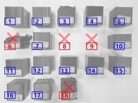
Table 3의 18개 설계변수 조합에 따라 출력된 조형물은
Fig. 6에서 사진으로 표현되어 있다.
Fig. 6에서 확인할 수 있듯 설계 변수 조합 6, 8, 9 및 10에서는 정상적인 적층이 이루어지지 못해 그 형태가 유지되지 않은 조형물도 존재하며, 그 경우 표면 조도 측정이 불가능하여 민감도 분석을 위해 표면 조도의 값을 30 μm로 강제 부여하였다.
Fig. 6Sculptures printed through experiments
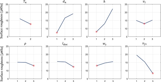
3.2 민감도 분석
Fig. 7은 각 공정 설계변수들의 표면 조도에 대한 민감도 분석 결과이며, 다른 설계변수 대비 B, C, H는 표면 조도에 유의미한 민감도를 갖는 것으로 확인되었다. 따라서, 결과에 따라 가장 민감한 적층 설계변수 Nozzle Diameter (d
n)와 Layer Height (h) 설계변수 사이의 Interaction을 확인한다. 이를 위해 d
n의 최적 수준(1.0 mm)을 기준으로 하는 구간(0.8, 1.0, 1.2 mm) 3 수준과 마찬가지로 최적 수준 h의 주위 3 수준(5, 10, 15%)를 추가로 선정하여 두 설계변수 사이의 교호작용 여부를 확인하였다.
Fig. 7Result of the level-average analysis: Independent sensitivities of all process parameters to the surface roughness
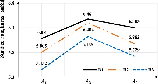
그 결과
Fig. 8과 같이 설계변수 d
n의 변화와 상관없이 h의 값은 일정하게 변화하였다. 즉, 두 인자 사이의 평행성이 확인되므로 두 설계변수 사이의 교호작용은 없다고 할 수 있다.
Fig. 8Confirm the interaction between parameters dn and h
민감도 분석을 통해 아래
Table 4와 같은 최적의 설계변수 조합을 도출하였고, 이를 통해 적층-정삭 공정을 수행하였다. 그 결과, 조형물의 표면 조도는 5.8922 μm로 측정되었으며, 이는 오직 적층만 수행하였을 때 조형물의 표면 조도보다 86% 향상된 값이다.
Table 4Optimal design parameter combination
Table 4
|
Parameter |
Tn
|
dn
|
h |
vl
|
ρ |
ldoc
|
ws
|
vfr
|
|
Value |
210 |
1.0 |
10 |
60 |
60 |
70 |
520 |
40 |
3.3 효과 분석
Table 5에는 최적 설계변수 조합으로 적층-정삭 공정을 수행한 조형물과 고품질 적층물의 표면 조도 및 조형 시간 결과가 비교 및 분석되어 있다. 적층-정삭 조형물의 표면 조도가 고품질 출력물보다 최대 87% 향상된 것을 확인하였다. 조형 시간 또한 고품질 출력을 위해 사용하였던 기존 0.4-0.8 mm 노즐 직경들에 비해 최대 70% 향상됨을 확인하였다. 이를 통해 단순 고품질 적층만을 수행하였을 때보다 저품질 쾌속 조형 후 정삭 후처리 공정을 수행한 조형물이 표면 조도와 조형 시간 모두가 향상됨을 확인하였다.
Table 5Surface roughness and printing time improvement by finishing process
Table 5
|
Optimal parameter set |
|
Nozzle diameter
[mm] |
Surface roughness
[μmSa] |
Printing time
[min] |
|
1.0 |
5.8922 |
80 |
|
Only additive |
|
Nozzle diameter
[mm] |
Surface roughness [μmSa]
(Improvement [%]) |
Printing time [min]
(Improvement [%]) |
|
0.4 |
41.88 (86) |
264 (70) |
|
0.6 |
45.74 (87) |
183 (56) |
|
0.8 |
42.22 (86) |
121 (34) |
앞서 실험에서 적층물의 형상이 유지가 되지 않는 경우에 표면 조도를 30 μmSa로 강제 부여하여 민감도 분석을 진행하였다. 이에, d
n이 1.5 mm으로 설정된 6번 실험에서 형상이 무너짐에 따라 설계변수 민감도 분석 시 d
n이 1.5 mm일 경우 최적 수준으로 분석되지 않았다. 따라서, 1.0 mm 노즐이 최적 파라미터 조합으로 선정되었지만, 1.5 mm 노즐의 조합인 14번 조합에서도 형상 유지가 가능한 조형물이 존재하였다. 그 실험의 결과를
Table 6에 정리하였고, 적층 시간은 23분으로 71% 적은 것으로 나타나 있다. 이를 통해 쾌속 조형이 우선시되어 실험이 진행될 경우 선택적인 1.5 mm 노즐의 사용 또한 고려할 필요가 있다.
Table 6Comparison between the optimal case and case No. 14
Table 6
|
Case |
Nozzle diameter
[mm] |
Printing time
[min] |
Surface
roughness
[μmSa] |
|
Optimal case |
1.0 |
80 |
5.8922 |
|
Case No. 14 |
1.5 |
23 |
8.8527 |
4. 결론
본 논문에서는 FDM 출력물의 표면 품질과 생산성 향상을 위한 표면 정삭 공정 시의 적층 및 정삭 설계변수의 최적 조합을 선정하고, 이에 따른 고품질 출력 대비 표면 조도와 조형 시간의 향상 정도를 확인하였다. 이를 위해 적층 설계변수로 Nozzle Diameter, Layer Height, Speed of Laminating, Infill Density 및 Nozzle Temperature를 정의하고, 정삭 설계변수로 Depth of Cut, Spindle RPM과 Feed Rate를 정의하였다. 적층 및 정삭 설계변수의 최적 조건을 탐색하기 위해 3 수준 직교배열표를 작성하여 실험계획을 수립하여 실험을 수행하였다.
그 결과, 표면 품질에 Nozzle Diameter, Layer Height와 Feed Rate가 큰 영향을 미치는 것으로 확인하였고, 이를 바탕으로 최적 조합에서 적층-정삭 공정을 수행하였을 때가 단순 고품질 적층에 비해 조형 시간은 7%, 표면 조도는 86% 향상됨을 확인하였다. 따라서 FDM 출력물에 정삭 공정을 추가함으로써 표면 조도와 조형 시간 모두 향상시킬 수 있음을 검증하였으며 추후 연구로써 적층-정삭 공정이 일체화된 3D 프린팅 플랫폼을 직접 제작하여 실험을 수행할 예정이다.
ACKNOWLEDGMENTS
이 논문은 산업통상자원부 ‘산업혁신인재성장 지원사업’의 재원으로 한국산업기술진흥원(KIAT)의 지원과 2021년도 정부(산업통상자원부)의 재원으로 한국산업기술진흥원의 지원을 받아 수행된 연구임(2021년 산업 융합형 웨어러블 스마트 디바이스 전문인력 양성사업, No. P0002397) (2021년 데이터분석기반의 전자제조 전문인력양성사업, No. P0017123).
REFERENCES
- 1.
Lee, I. H., Kim, H.-C., and Ahn, D.-G., “Korean Terminologies for Additive Manufacturing according to the ISO/ASTM 52900 Standard,” Journal of the Korean Society for Precision Engineering, Vol. 37, No. 12, pp. 929-936, 2020.
10.7736/JKSPE.020.093
- 2.
Dudek, P., “FDM 3D Printing Technology in Manufacturing Composite Elements,” Archives of Metallurgy and Materials, Vol. 58, No. 4, pp. 1415-1418, 2013.
10.2478/amm-2013-0186
- 3.
Jeong, H., Yu, J., and Lee, D., “Calibration of In-Plane Center Alignment Errors in the Installation of a Circular Slide with Machine-Vision Sensor and a Reflective Marker,” Sensors, Vol. 20, No. 20, Paper No. 5916, 2020.
10.3390/s20205916
- 4.
Lee, S., Shin, C., Jung, M., and Park, M., “Property Analysis of Multi-Material Specimen based on ME Type 3D Printer,” Journal of the Korean Society for Precision Engineering, Vol. 37, No. 3, pp. 231-238, 2020.
10.7736/JKSPE.019.122
- 5.
Lalehpour, A., Janeteas, C., and Barari, A., “Surface Roughness of FDM Parts after Post-Processing with Acetone Vapor Bath Smoothing Process,” The International Journal of Advanced Manufacturing Technology, Vol. 95, No. 1, pp. 1505-1520, 2018.
10.1007/s00170-017-1165-5
- 6.
Valerga, A. P., Batista, M., Fernandez-Vidal, S. R., and Gamez, A. J., “Impact of Chemical Post-Processing in Fused Deposition Modelling (FDM) on Polylactic Acid (PLA) Surface Quality and Structure,” Polymers, Vol. 11, No. 3, Paper No. 566, 2019.
10.3390/polym11030566
- 7.
Kim, M. K., Lee, I. H., and Kim, H.-C., “Effect of Fabrication Parameters on Surface Roughness of FDM Parts,” International Journal of Precision Engineering and Manufacturing, Vol. 19, No. 1, pp. 137-142, 2018.
10.1007/s12541-018-0016-0
- 8.
Buj-Corral, I., Domínguez-Fernández, A., and Durán-Llucià, R., “Influence of Print Orientation on Surface Roughness in Fused Deposition Modeling (FDM) Processes,” Materials, Vol. 12, No. 23, Paper No. 3834, 2019.
10.3390/ma12233834
- 9.
Lalegani Dezaki, M., Mohd Ariffin, M. K. A., and Ismail, M. I. S., “Effects of CNC Machining on Surface Roughness in Fused Deposition Modelling (FDM) Products,” Materials, Vol. 13, No. 11, Paper No. 2608, 2020.
10.3390/ma13112608
- 10.
Adeniji, D., Schoop, J., Gunawardena, S., Hanson, C., and Jahan, M., “Characterization and Modeling of Surface Roughness and Burr Formation in Slot Milling of Polycarbonate,” Journal of Manufacturing and Materials Processing, Vol. 4, No. 2, Paper No. 59, 2020.
10.3390/jmmp4020059
- 11.
Saad, M. S., Nor, A. M., Baharudin, M. E., Zakaria, M. Z., and Aiman, A., “Optimization of Surface Roughness in FDM 3D Printer Using Response Surface Methodology, Particle Swarm Optimization, and Symbiotic Organism Search Algorithms,” The International Journal of Advanced Manufacturing Technology, Vol. 105, No. 12, pp. 5121-5137, 2019.
10.1007/s00170-019-04568-3
- 12.
Huynh, L. P., Nguyen, H. A., Nguyen, H. Q., Phan, L. K., and Thanh, T. T., “Effect of Process Parameters on Mechanical Strength of Fabricated Parts Using the Fused Deposition Modelling Method,” Journal of the Korean Society for Precision Engineering, Vol. 36, No. 8, pp. 705-712, 2019.
10.7736/KSPE.2019.36.8.705
- 13.
Turner, B. N., Strong, R., and Gold, S. A., “A Review of Melt Extrusion Additive Manufacturing Processes: I. Process Design and Modeling,” Rapid Prototyping Journal, Vol. 20, No. 3, pp. 192-204, 2014.
10.1108/RPJ-01-2013-0012
- 14.
Lee, C.-W., Kim, H.-W., Yu, J.-H., and Park, K., “Thermal-Fluid Coupled Analysis of the Nozzle Part for the FDM 3D Printers considering Flow Characteristics of Cooling Fan,” Journal of the Korean Society for Precision Engineering, Vol. 35, No. 5, pp. 479-484, 2018.
10.7736/KSPE.2018.35.5.479
- 15.
Barrios, J. M. and Romero, P. E., “Improvement of Surface Roughness and Hydrophobicity in PETG Parts Manufactured via Fused Deposition Modeling (FDM): An Application in 3D Printed Self-Cleaning Parts,” Materials, Vol. 12, No. 15, Paper No. 2499, 2019.
10.3390/ma12152499
- 16.
van Manen, T., Janbaz, S., and Zadpoor, A. A., “Programming the Shape-Shifting of Flat Soft Matter,” Materials Today, Vol. 21, No. 2, pp. 144-163, 2018.
10.1016/j.mattod.2017.08.026
- 17.
Dey, A. and Yodo, N., “A Systematic Survey of FDM Process Parameter Optimization and Their Influence on Part Characteristics,” Journal of Manufacturing and Materials Processing, Vol. 3, No. 3, Paper No. 64, 2019.
10.3390/jmmp3030064
- 18.
Ali, F., Chowdary, B. V., and Maharaj, J., “Influence of Some Process Parameters on Build Time, Material Consumption, and Surface Roughness of FDM Processed Parts: Inferences based on the Taguchi Design of Experiments,” Proc. of the IACJ/ISAM Joint International Conference, 2014.
- 19.
Shin, D.-Y. and Song, C.-H., “Performance Optimization of Down-the-Hole Hammer Using Taguchi Method,” Transactions of the Korean Society of Mechanical Engineers A, Vol. 36, No. 1, pp. 109-116, 2012.
10.3795/KSME-A.2012.36.1.109
- 20.
Gwon, J. Y., Lee, E. S., and Kwon, W. T., “Optimization of Performance Using Taguchi Method and Grey Relational Analysis in Micro-EDM Using Copper Electrode,” Journal of the Korean Society for Precision Engineering, Vol. 35, No. 8, pp. 737-743, 2018.
10.7736/KSPE.2018.35.8.737
- 21.
Hwang, G.-H., Gwon, U., Lee, G.-H., and Park, G.-J., “Design of Structure Using Orthogonal Array considering Interactions in Discrete Design Spaces,” Transactions of the Korean Society of Mechanical Engineers A, Vol. 24, No. 12, pp. 2952-2962, 2000.
- 22.
Song, C. Y. and Lee, D.-J., “A Comparative Study on Surrogate Models and Sensitivity Analysis for Structure Design of Automatic Salt Collector Using Orthogonal Array Experiment,” Journal of Convergence for Information Technology, Vol. 10, No. 7, pp. 138-146, 2020.
Biography
- Ji Won Yu
MS candidate in the Department of Mechanical Engineering, Soongsil University. Her research interest is additive manufacturing, machine vision, robot kinematic mechanism and robot calibration.
- Hyung Jin Jeong
MS candidate in the Department of Mechanical Engineering, Soongsil University. His research interest is additive manufacturing, robot kinematic mechanism and robot calibration.
- Jae Hyung Park
B.Sc. candidate in the Department of Mechanical Engineering, Soongsil University. His research interest is additive manufacturing.
- Dong Hun Lee
Professor in the Department of Mechanical Engineering, Soongsil University. His research interest is machine learning, collaborative robot, human motion recognition, mobile platform, and redundant mechanism.