ABSTRACT
The objective of this study was to present a rotary manipulating system driven by a rotary actuator based on twisted shape memory alloy (SMA) wires. The rotary actuator was composed of two oppositely twisted SMA wires connecting a rotor and a stator through a shaft. Two oppositely twisted SMA wires could generate bidirectional rotary motions upon actuation of each twisted SMA wire corresponding to the direction against the twist direction of each SMA wire. A manipulator was designed and fabricated by integrating manipulating arms, the rotary actuator, and a Hall effect magnetic rotary encoder which could measure the angular position of the rotary motion. We modeled and characterized the manipulator upon application of a ramp current input to each twisted SMA wire. A proportional-integral-derivative (PID) controller was designed and implemented to control the proposed rotary manipulator. Reference angular position tracking performances of the manipulator were evaluated with a series of experiments.
-
KEYWORDS: Shape memory alloy, Rotary actuator, Manipulator, PID control
-
KEYWORDS: 형상기억합금, 회전 구동기, 매니퓰레이터, PID 제어
1. Introduction
For decades, shape memory alloy (SMA) has gathered intense research interests for many scientific and engineering applications, for examples, composites
[1-
3]; robotics
[4-
7]; biomimetics
[5,
8]; biomedical
[9]; and wearable devices
[10,
11]. SMA exhibits large deformation with relatively high power density and can be easily integrated into the structures as many available forms (wire, sheet, etc.)
[4,
6,
12-
14]. At low temperature, SMA is represented by the twinned Martensite without external stresses or loads
[13,
14]. And it is deformable to the detwinned Martensite by external loads at low temperature
[13,
14]. The deformed (detwinned) SMA is restored to its original shape by applying heat, and it is called the shape memory effect (SME)
[13,
14].
The property enables SMA applicable for the actuators. In many practical applications, actuation mechanism based on the axial contraction of the SMA wire has been preferred
[1,
3,
4,
6,
15]. Recently, we proposed a new actuation mechanism for a rotary actuator based on the twisted SMA wires
[16], reporting the design and fabrication processes with actuation performances of the rotary actuator.
In the present work, we designed and fabricated a rotary manipulating system driven by a rotary actuator based on the twisted SMA wires. The rotary actuator is composed of two oppositely twisted SMA wires connecting rotor and stator through a shaft. The two oppositely twisted SMA wires generate bidirectional rotary motions upon actuation of each twisted SMA wire corresponding to the direction against the twist direction of each SMA wire. A simple manipulating system was designed and fabricated by integrating the manipulating arms, the rotary actuator, and a Hall effect magnetic rotary encoder which measures the angular position of the rotary motion. We modeled and characterized the transfer function of the manipulating system upon the application of ramp current input to each twisted SMA wire. A proportional-integral-derivative (PID) controller was designed and implemented for the proposed rotary manipulating system. The reference angular position tracking performances of the manipulating system were evaluated with varying the angular velocity and the maximum angular position of the reference ramp inputs.
2. Design and Fabrication of the Rotary Actuator and Manipulating System
2.1 Design and Fabrication of the Rotary Actuator using Twisted SMA Wires
In our earlier report, we proposed a rotary actuator prepared by the twisted SMA wires, with presenting its actuation mechanism; design; fabrication processes; and actuation performances
[16]. For the present work, we further developed the technique for a rotary manipulator driven by the similar rotary actuator integrated with the sensor and controller.
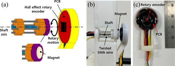
Fig. 1(a) shows the rotary actuator unit designed and used for the present work. The two oppositely twisted SMA wires (200 μm diameter Flexinol® SMA wire with 70
oC of phase transition temperature, Dynalloy, Inc.), denoted by twisted SMA wire 1 and 2, respectively, are folded and adhered through the holes in the rotor and the stator. A UV curable resin (JJOMA UV Resin, Jjomanhan – Maeul) was used for the adhesion. We attached a magnet assembly on top of the rotor so that it generates a magnetic field on the rotary encoder, which senses the angular position of the rotary actuator. A shaft connects the rotor and the stator through their center. The fabricated rotary actuator units are presented in
Fig. 1(b).
Fig. 1(c) shows the actuator units with the magnet assembly attached.
Fig. 1(a) A 3D model of the designed rotary actuator. (b) Photo of the fabricated rotary actuator. (c) The rotary actuator with the magnet assembly. (d) The oppositely twisted SMA wires. (e) The twisted SMA wires applied with the UV curable resin and the electrical leads. (f) Photo of the rotor and shaft. (g) Photo of the magnet assembly
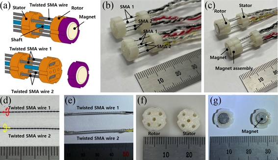
We provide an optical image of the two oppositely twisted SMA wires in
Fig. 1(d). Those twisted SMA wires were fabricated by using the same setup and procedures reported in our earlier report
[16]. A stepping motor was used to twist the SMA wires (approximately 80 mm long), and the rotating direction of the stepping motor controls the twist direction. The twisted SMA wire generates rotary motion against the twist direction
[16]. For the present work, we used the revolutions of the stepping motor as 50, which results in approximately 2 mm of helix pitch within the twisted SMA wires. A UV curable resin is applied surrounding the twisted SMA wires for insulating them during the actuation as shown in
Fig. 1(e).
Figs. 1(f)-
1(g) present optical images of the 3D printed (ABS) rotor/stator, and the magnet assembly, respectively.
Fig. 2(a) presents a schematic of angular position measurement for the rotary actuator with a Hall effect magnetic rotary encoder. Upon the application of electric current to one of the twisted SMA wire, it generates rotary motion of the rotor about the shaft axis (against the twist direction). The magnet assembly rotates in the same direction. The rotary encoder detects the change of the magnetic field and measures the angular position of the rotor.
Fig. 2(b) presents the rotary actuator assembled with the rotary encoder and
Fig. 2(c) shows detailed view of the rotary encoder. We modified a commercially available rotary encoder (SME360CAP, SERA) for the present work.
Fig. 2(a) A schematical illustration of the rotary actuator with the rotary encoder. (b) Photo of the rotary actuator with the rotary encoder. (c) Detailed view of the rotary encoder

2.2 Design and Fabrication of the Rotary Manipulator
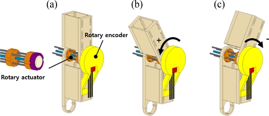
As presented in
Figs. 3(a)-
3(c), we designed a simple manipulating system composed of two rigid arms (fabricated by a 3D printer using ABS) assembled with the rotary actuator and the rotary encoder.
Figs. 3(a)-
3(c) schematically show how the upper manipulating arm rotates by the rotary motion of the rotary actuator. We used the sign convention for the rotary motions of the manipulating system as depicted in
Figs. 3(b)-
3(c).
Fig. 3A schematical illustration of the rotary manipulator with its rotational motions

The rotary actuator rotates the manipulator bidirectionally by application of electrical current to each twisted SMA wire. The rotary encoder integrated into the manipulator measures the angular position of the rotor.
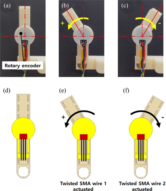
Figs. 4(a)-
4(c) capture the resulting rotary motions of the manipulating system upon sequential application of electrical current (1.5 A) to each twisted SMA wire (denoted by twisted SMA wire 1 and 2, respectively) with schematic representations in
Figs. 4(d)-
4(f).
Fig. 4(a)-(c) The fabricated rotary manipulator and the resulting rotary motions generated by the applied electric current to the twisted SMA wires in the rotary actuator. (d)-(f) Schematic illustrations of the rotary motions of the manipulator

3. Experimental Setup
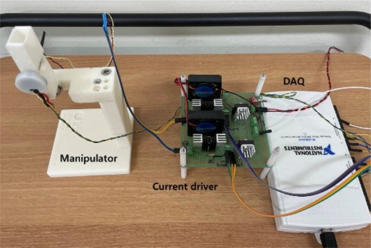
An experimental setup composed of the rotary manipulator, a custom-made current driver, and a DAQ board (NI-USB6211) was built and used for the experiments;
Fig. 5 presents the experimental setup. We built and used a custom software to drive and control the rotary manipulator by using LabView.
Fig. 5 Experimental setup composed of the manipulator, current driver, and DAQ system
4. Results and Discussions
4.1 Characterization of the Rotary Manipulator
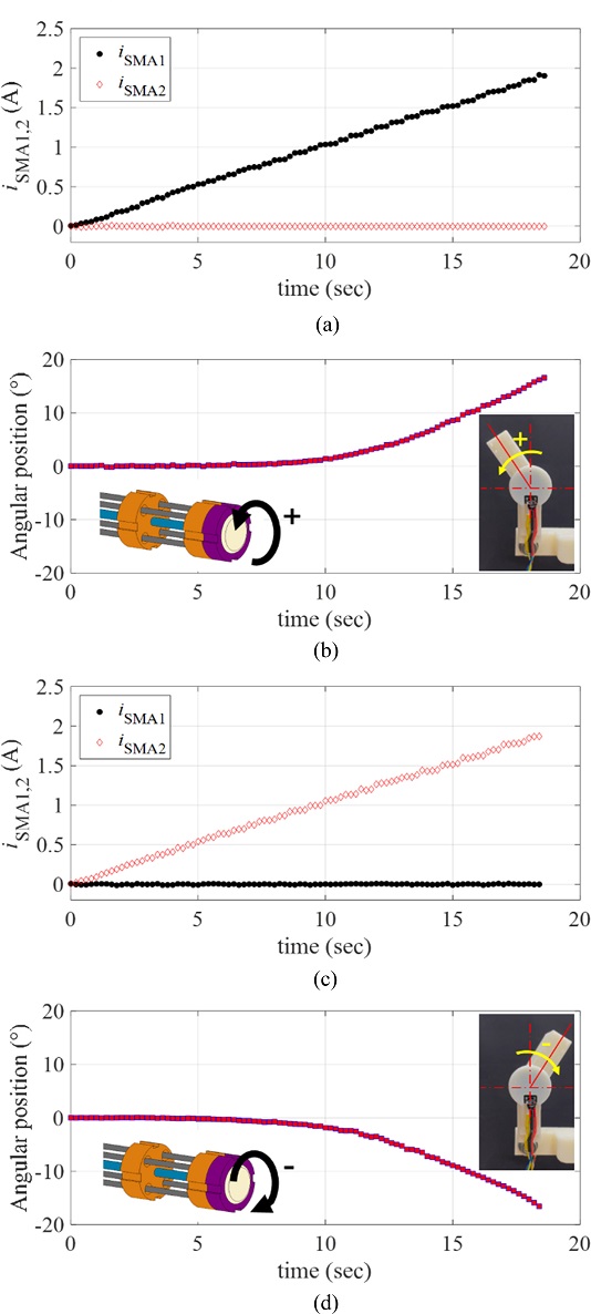
To characterize the response of the manipulator driven by the proposed rotary actuator, we applied a ramp current input to each twisted SMA wire (denoted by iSMA1 and iSMA2, respectively). We defined the positive rotating direction of the actuator as the rotating direction corresponds to the twisted SMA wire 1; denoted by SMA1. For the positive rotary motion, we applied the ramp current input to the SMA1 as iSMA1(t) = 0.1t A for 18 sec, while the current to the SMA2 was zero.
Fig. 6(a) plots the applied currents (
iSMA1 and
iSMA2) to the twisted SMA wires.
Fig. 6(b) provides the resulting angular position of the manipulating arm in the positive direction, measured by the rotary encoder. For the negative rotary motion, we applied the same ramp current input to the SMA2 as
iSMA2(
t) = 0.1
t A for 18 sec, while the current to the SMA1 was zero as shown in
Fig. 6(c).
Fig. 6(d) captures the resulting angular position of the manipulating arm in the negative direction, measured by the rotary encoder. As shown in
Figs. 6(b) and
6(d), there exists the minimum current level from which the angular position starts to be recognizable (approximately 0.5 A and 0.3 A for the positive and negative directions, respectively). In other words, the rotary motions of the SMA wires are not initiated at the input current smaller than those values. It is expected that the temperature-induced phase transformation of the SMA wire is not sufficiently initiated at the electrical current smaller than those values.
Fig. 6(a), (c) The current input to the twisted SMA wires, and (b), = [ + ] (d) the resulting angular position of the manipulator; (b) motion in the positive direction, (c) motion in the negative direction

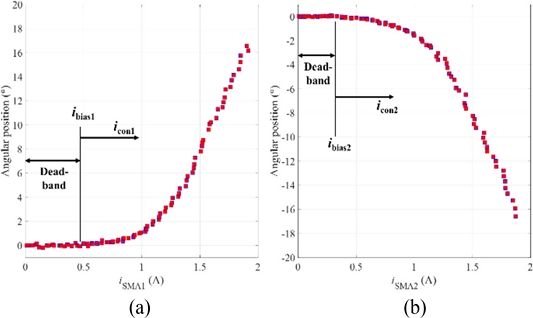
We also plotted the measured angular position of the rotary actuator with respect to the amplitude of the input current in
Figs. 7(a)-
7(b). As the input current had values from zero to specific values (approximately, 0.45 A and 0.3 A for the positive and negative rotating directions, respectively), the rotary actuator showed nearly zero angular motions. The rotary actuator started to rotate the manipulating arm at the input currents larger than those values. We define the dead-band of the rotary actuator at which it does not respond (or its response is negligible) to the input current. The upper bounds of the dead-band are defined as the bias currents (denoted by
ibias1 and
ibias2 for the SMA1 and SMA2, respectively). And the control inputs to each twisted SMA wire (denoted by
icon1 and
icon2 for the SMA1 and SMA2, respectively in
Fig. 7) are used to model the system response upon the ramp input was applied.
Fig. 7Angular position of the rotary actuator with respect to the amplitude of the input current (a) in the positive, (b) in the negative directions

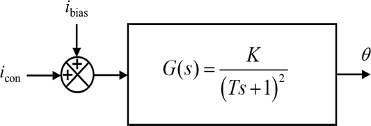
The resulting block diagram of the rotary manipulating system is presented in
Fig. 8. We modeled the rotary manipulator as a critically damped second order system with the gain
K and the time constant
T. The response of the system upon the application of the ramp input
icon(
t) = 0.1
t is obtained as in
Equation (1) [17].
Fig. 8Block diagram representation of the rotary manipulating system

We plotted the ramp responses of the rotary actuator in the positive and negative directions in terms of the control inputs
icon1 and
icon2 in
Fig. 9, where
icon1(
t) =
icon2(
t) = 0.1
t A. The model fitted responses following
Equation (1) are plotted together in
Figs. 9(b) and
9(d) with the experimental data.
Table 1 summarizes the fitting coefficients
K and
T of the model obtained by nonlinear least square curve fits, with the coefficient of determination
R2.
Fig. 9(a), (c) The ramp inputs to the rotary manipulator icon1 and icon2, and (b), (d) the ramp responses of the rotary actuator in the (b) positive and (d) negative directions with the model fits
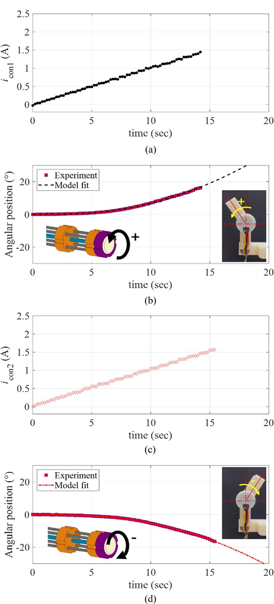
Table 1The system parameters obtained from the model fits of the ramp responses
Table 1
|
Positive direction |
Negative direction |
|
K
|
83.4797 |
105.3464 |
|
T
|
11.5931 |
15.6548 |
|
R
2
|
0.9986 |
0.9989 |
The system parameters (K and T) obtained from the ramp responses showed small variations between the positive and negative directions. We expect those variations are mainly caused by the quality variations in the manufacturing processes of each twisted SMA wire, and the manipulator assembly.
4.2 Controller Design and Performance Evaluations
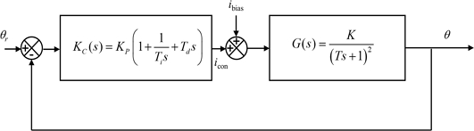
We implemented a PID controller to the rotary manipulator and evaluated the reference angular position tracking performances. The block diagram of the feedback control system with the PID controller is shown in
Fig. 10.
Fig. 10Block diagram representation of the feedback control system
We first designed a PI controller with the controller gain
KP and the integral time
Ti based on the Ziegler-Nichols tuning rules
[17]. And a small derivative action with the derivative time
Td was added to the controller. For the gain tuning, the average values of the system parameters (
K and
T) in the positive and negative directions obtained from the ramp responses were used. The resulting controller gain
KP, integral time
Ti, and derivative time
Td are summarized in
Table 2.
Table 2The gain, integral time, and derivative time of the PID controller
Table 2
|
Controller parameter |
Value |
|
K
P
|
0.90 |
|
Ti [sec] |
45.41 |
|
Td [sec] |
0.60 |
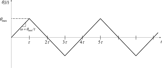
To evaluate the performance of the control system, we considered the ramp reference angular position
θr(
t) as shown in
Fig. 11. The slope of the ramp reference input is defined by the angular velocity
ω =
θmax/
t, and we varied the angular velocity
ω and the maximum angular position
θmax for the experiments.
Fig. 11Schematic representation of the ramp reference angular position
We implemented the designed PID controller with a custom-made control software using LabView and captured the angular position of the manipulator upon the applications of ramp reference inputs. The maximum current input to the twisted SMA wires was limited by 2 A to prevent overheating and failures of the SMA wires.
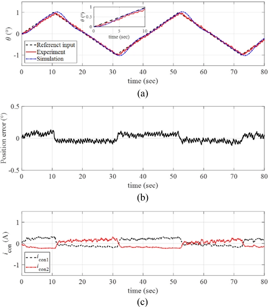
Fig. 12(a) plots the response of the manipulator obtained from the reference angular position tracking experiments by setting the angular velocity and the maximum angular position of the ramp reference input as
ω = 0.1
o/sec and
θmax = 1
o, respectively. The inset in
Fig. 12(a) shows the magnified image of the data. We conducted numerical simulations of the response using MATLAB and the simulated response is plotted together in
Fig. 12(a). The control system follows the reference angular position well with small position error as shown in
Fig. 12(b).
Fig. 12(c) presents the control input currents to each twisted SMA wire during the experiments.
Fig. 12(a) Response of the manipulator with the reference input and the simulated signals (ω = 0.1o/sec and θmax = 1o). (b) Position error. (c) The control inputs to each twisted SMA wire. Inset in (a) magnified image of the data

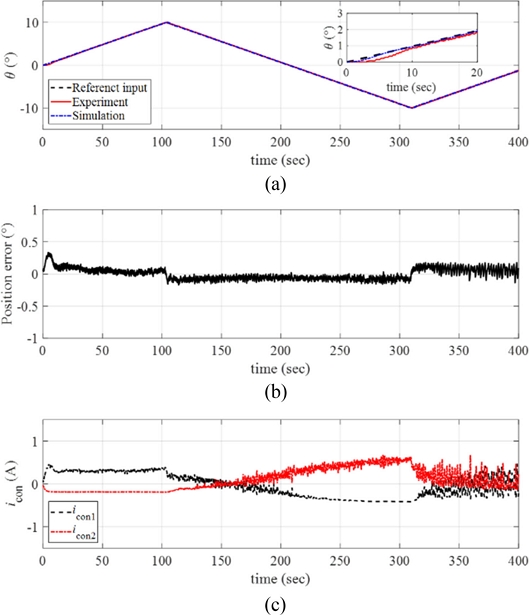
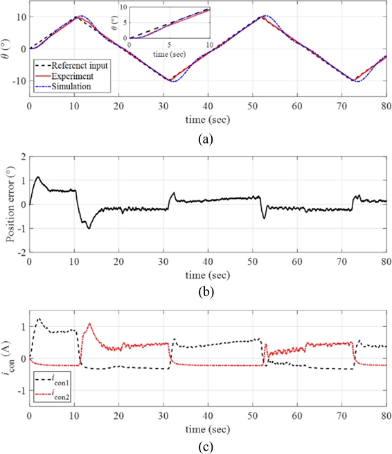
We increased the maximum angular position of the ramp reference input
θmax = 10
o with the same angular velocity
ω = 0.1
o/sec. The results are plotted in
Fig. 13(a) along with the simulated signals. As the magnitude of the reference input increased to 10
o, the response of the control system still follows the reference input well; see position error presented in
Fig. 13(b).
Fig. 13(c) plots the control input currents to each twisted SMA wire during the experiments, and we observe the increases in the control inputs for the manipulator to follow larger reference inputs.
Fig. 13(a) Response of the manipulator with the reference input and the simulated signals (ω = 0.1o/sec and θmax = 10o). (b) Position error. (c) The control inputs to each twisted SMA wire. Inset in (a) magnified image of the data

We conducted experiments with faster angular velocity of the ramp reference input as
ω = 1
o/sec.
Fig. 14(a) captures the angular position of the manipulator with the reference ramp input (where
θmax = 10
o) and the simulated signals. As presented in
Fig. 14(b), the response of the manipulator exhibits relatively larger position error compared to the results with slower angular velocity.
Fig. 14(c) plots the control input currents during the experiments. Referring to
Fig. 14(c), larger control inputs are required for tracking faster angular velocity of the reference input.
Fig. 14(a) Response of the manipulator with the reference input and the simulated signals (ω = 1o/sec and θmax = 10o). (b) Position error. (c) The control inputs to each twisted SMA wire. Inset in (a) magnified image of the data

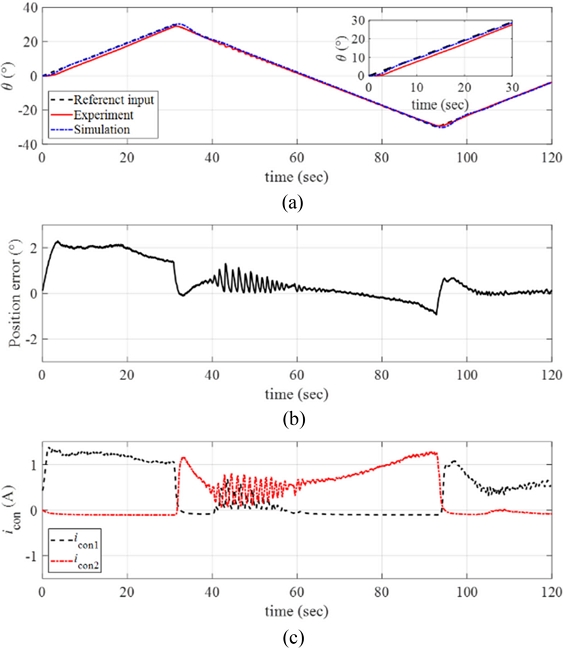
The maximum angular position of the ramp input was further increased to
θmax = 30
o with the same angular velocity (
ω = 1
o/sec), and the experimental results are plotted in
Fig. 15(a) with the position error in
Fig. 15(b) and the control inputs in
Fig. 15(c). The manipulator followed the reference position with position error smaller than 2
o as shown in
Fig. 15(b). The control currents required higher values for tracking larger magnitude of the reference input.
Fig. 15(a) Response of the manipulator with the reference input and the simulated signals (ω = 1o/sec and θmax = 30o). (b) Position error. (c) The control inputs to each twisted SMA wire. Inset in (a) magnified image of the data

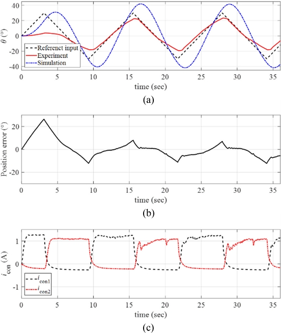
Finally, much faster reference input was considered with the angular velocity
ω = 10
o/sec. We applied the maximum angular position of the ramp reference input as
θmax = 30
o. The resulting response of the rotary manipulator is presented in
Fig 16(a) with the position error and the control inputs in
Figs. 16(b) and
16(c), respectively. Referring to
Figs. 16(a)-
16(b), the manipulator could not sufficiently follow the faster reference input and large position error was observed during the motions. Since we limited the current input to the SMA wire (
iSMA =
ibias +
icon) as
iSMA,max = 2 A, we observed almost saturated control input currents during the motions.
Fig. 16(a) Response of the manipulator with the reference input and the simulated signals (ω = 10o/sec and θmax = 30o). (b) Position error. (c) The control inputs to each twisted SMA wire

It is noted that further tunes of the controller gains with considering advanced controllers will improve the reference tracking performance of the system. We remain the related studies for our future works.
5. Conclusions
In this study, we presented design and fabrication of a rotary manipulator driven by a rotary actuator based on the twisted SMA wires. The dynamic response of the manipulator was characterized by ramp response, and a PID controller was implemented for the position control of the manipulator. The reference angular position tracking performances of the manipulating system were evaluated upon the ramp reference inputs applied with varying the angular velocity and the maximum angular position of the ramp input. The proposed manipulator reliably followed the reference input with position error smaller than 2o up to 30o of the maximum angular position under 1o/s of the angular velocity. While the proposed rotary actuator has benefits for miniaturization; integration into the assembly; with its relatively easy control of the bidirectional motion, it has limited operating range and has difficulties for achieving continuous rotary motion with the present form, when it is compared to conventional electric motors. Further studies for overcoming the limitations with the improvements of the performance by re-designing and improving the manipulator with the controller will be followed as our future works.
ACKNOWLEDGMENTS
This research was supported by the National Research Foundation of Korea (NRF) grant funded by the Korea government (MEST) (No. NRF-2020R1A2C4001731) and Kumoh National Institute of Technology (No. 202001090001).
REFERENCES
- 1.
Rodrigue, H., Wang, W., Bhandari, B., Han, M.-W., Ahn, S.-H., (2015), SMA-based smart soft composite structure capable of multiple modes of actuation, Composites Part B: Engineering, 82, 152-158.
10.1016/j.compositesb.2015.08.020
- 2.
Ashir, M., Cherif, C., (2020), Development of shape memory alloy-based adaptive fiber-reinforced plastics by means of open reed weaving technology, Journal of Reinforced Plastics and Composites, 39(15-16), 563-571.
10.1177/0731684420920941
- 3.
Han, M.-W., Kim, M.-S., Ahn, S.-H., (2020), Shape memory textile composites with multi-mode actuations for soft morphing skins, Composites Part B: Engineering, 198, 108170.
10.1016/j.compositesb.2020.108170
- 4.
Lee, J.-H., Chung, Y. S., Rodrigue, H., (2019), Long shape memory alloy tendon-based soft robotic actuators and implementation as a soft gripper, Scientific Reports, 9(1), 11251.
10.1038/s41598-019-47794-1
- 5.
Koh, J.-S., Cho, K.-J., (2012), Omega-shaped inchworm-inspired crawling robot with large-index-and-pitch (LIP) SMA spring actuators, IEEE/ASME Transactions On Mechatronics, 18(2), 419-429.
10.1109/TMECH.2012.2211033
- 6.
Song, S.-H., Lee, J.-Y., Rodrigue, H., Choi, I.-S., Kang, Y. J., Ahn, S.-H., (2016), 35 Hz shape memory alloy actuator with bending-twisting mode, Scientific reports, 6(1), 21118.
10.1038/srep21118
- 7.
Li, J., Zu, L., Zhong, G., He, M., Yin, H., Tan, Y., (2017), Stiffness characteristics of soft finger with embedded SMA fibers, Composite Structures, 160, 758-764.
10.1016/j.compstruct.2016.10.045
- 8.
Hwang, J., Wang, W. D., (2022), Shape memory alloy?based soft amphibious robot capable of seal?inspired locomotion, Advanced Materials Technologies, 7(6), 2101153.
10.1002/admt.202101153
- 9.
Zainal, M. A., Sahlan, S., Mohamed Ali, M. S., (2015), Micromachined shape-memory-alloy microactuators and their application in biomedical devices, Micromachines, 6(7), 879-901.
10.3390/mi6070879
- 10.
Jeong, J., Yasir, I. B., Han, J., Park, C. H., Bok, S.-K., Kyung, K.-U., (2019), Design of shape memory alloy-based soft wearable robot for assisting wrist motion, Applied Sciences, 9(19), 4025.
10.3390/app9194025
- 11.
Park, S. J., Park, C. H., (2019), Suit-type wearable robot powered by shape-memory-alloy-based fabric muscle, Scientific Reports, 9(1), 9157.
10.1038/s41598-019-45722-x
- 12.
Nespoli, A., Besseghini, S., Pittaccio, S., Villa, E., Viscuso, S., (2010), The high potential of shape memory alloys in developing miniature mechanical devices: A review on shape memory alloy mini-actuators, Sensors and Actuators A: Physical, 158(1), 149-160.
10.1016/j.sna.2009.12.020
- 13.
Jani, J. M., Leary, M., Subic, A., Gibson, M. A., (2014), A review of shape memory alloy research, applications and opportunities, Materials & Design (1980-2015), 56, 1078-1113.
10.1016/j.matdes.2013.11.084
- 14.
Soother, D. K., Daudpoto, J., Chowdhry, B. S., (2020), Challenges for practical applications of shape memory alloy actuators, Materials Research Express, 7(7), 073001.
10.1088/2053-1591/aba403
- 15.
Akbari, S., Sakhaei, A. H., Panjwani, S., Kowsari, K., Serjouei, A., Ge, Q., (2019), Multimaterial 3D printed soft actuators powered by shape memory alloy wires, Sensors and Actuators A: Physical, 290, 177-189.
10.1016/j.sna.2019.03.015
- 16.
Jang, E.-J., Lee, S.-Y., Kim, K.-H., Lee, G.-Y., (2022), Design and fabrication of a millimeter-scale rotary actuator based on the twisted shape memory alloy (SMA) wires, Journal of the Korean Society for Precision Engineering, 39(6), 403-410.
10.7736/JKSPE.022.034
- 17.
Ogata, K., (2010), Modern control engineering fifth edition, Prentice Hall.
Biography
- Gil-Yong Lee
Associate Professor in the Department of Mechanical Engineering, Kumoh National Institute of Technology. His research interests are integrated manufacturing system, sensors/actuators, composites, vibration, control, and additive manufacturing.
- Su-Yeon Lee
M.S. candidate in the Department of Mechanical Engineering, Kumoh National Institute of Technology. Her research interests are soft robotics, shape memory alloy, smart materials and structures.