ABSTRACT
Accurate localization in industrial environments is challenging due to factors such as dust and reflections that degrade perception. To overcome these limitations, we propose an environment-independent localization method that relies solely on ultra-wideband (UWB) positioning. Our system employs LiDAR-SLAM in an offline stage to create a global map frame and calibrate the transformation between this frame and the UWB anchors. During operation, the robot estimates its position using a Kalman filter applied to UWB measurements transformed into the map frame. This paper presents a preliminary feasibility study conducted in an office-like environment to verify the core calibration and localization pipeline. The results show that the proposed method effectively aligns UWB positions with a pre-built SLAM map, achieving a 94% reduction in root-mean-square error (RMSE) compared to raw UWB measurements when validated against LiDAR-SLAM ground truth. This initial verification establishes the technical viability of the framework and lays the groundwork for future validation in harsh, large-scale industrial settings.
-
KEYWORDS: Feasibility analysis, UWB-LiDAR SLAM calibration, UWB-based localization, Robot localization, Factory automation
-
KEYWORDS: 기초 타당성 검토, UWB-LiDAR SLAM 보정, UWB 기반 위치 추정, 로봇 위치 추정, 공장 자동화
1. Introduction
Accurate localization is a fundamental requirement for autonomous mobile robots operating in structured and unstructured environments. Among various sensing methods, LiDAR and vision-based approaches are widely used due to their high spatial resolution and capability to provide rich environmental information. Despite the advancements in LiDAR or vision-based SLAM, their real-world application in industrial environments is often hindered by significant operational constraints. First, environmental degradation such as heavy dust, welding smoke, or drastic lighting changes can scatter LiDAR beams and render visual features unrecognizable. Second, visibility constraints make landmark-based systems like AprilTags or ArUco markers impractical in cluttered factories, a clear line-of-sight to these markers is frequently blocked by moving machinery, high-shelf cabinets, or personnel. Therefore, a localization technique that operates independently of environmental variations is essential for achieving robust performance in real-world applications.
Ultra-wideband (UWB) technology has recently attracted attention as an alternative or complementary solution for localization in environments where perception sensing is unreliable. Several studies have applied UWB-based localization with filtering or sensor fusion techniques to improve accuracy [
1-
9], and others have investigated combining UWB with other sensors for enhanced robustness [
10,
11]. However, most of these approaches require simultaneous operation of multiple sensors like LiDAR, limiting their applicability in environments where LiDAR or cameras cannot function reliably. Moreover, few studies have focused on the calibration between UWB and LiDAR SLAM coordinate systems to enable consistent localization within prebuilt global map [
12].
Furthermore, continuous online SLAM requires high computational power and is prone to ‘breaking’ when the environment becomes too dynamic or featureless. To address these limitations, this study proposes a calibration-based localization approach that leverages a pre-built SLAM map obtained once during an offline stage and relies solely on UWB measurements for online localization. During the offline phase, a SLAM system-such as LiDAR-Inertial SLAM (DLIO) [
13], visual-SLAM, or any mapping method-is used to establish a highprecision ‘Gold Standard’ map and to estimate the rigid-body transformation between the SLAM map frame and the UWB anchor frame. Once the UWB anchors are calibrated to this global frame, the robot can transition to a perception-independent online mode. This UWB-only approach provides a perceptionindependent localization alternative that remains operational even when traditional perception sensors fail, ensuring continuous safety and navigation reliability in perception-challenging workspaces. Although recent studies, such as Zhu et al. (2022) [
14], have proposed tightly coupled UWB/LiDAR-SLAM integration to achieve high-precision localization by fusing multiple data streams in real-time. While such fusion methods significantly enhance SLAM accuracy in feature-rich environments, they require the continuous operation of perception sensors (LiDAR/Vision) during navigation. In constract, our approach does not require perception sensors during online navigation. The novelty of this method lies in its decoupled operational phases: LiDAR is utilized only once during an offline calibration stage to establish a persistent global reference frame for path planning. Subsequently, the robot navigates using UWBonly measurements during the online phase, ensuring operational continuity in extreme conditions where conventional tightlycoupled systems would otherwise degrade.
The main contributions of this study are summarized as follows.
(1) Anchor-tag-based UWB-SLAM calibration method:
We present a practical calibration procedure that estimates the rigid transformation between the UWB anchor frame and the SLAM map frame using only anchor-tag distance measurements. This approach requires only a small subset of non-collinear anchors, facilitating setup in various indoor workspaces.
(2) UWB-only map-frame localization pipeline:
We develop a lightweight localization pipeline relying solely on UWB-provided 2D positions and a constant-velocity Kalman filter. No LiDAR, vision, or inertial sensing is required during online operation, which is intended to maintain stability where perception sensors might fail.
(3) Preliminary verification in a representative indoor workspace:
The proposed framework is validated through pilot experiments in an office-like environment. These results confirm the technical feasibility and basic applicability of map-consistent UWB-only localization, serving as a foundational step toward future industrial field applications.
2. Method
2.1 Overview of the Proposed Method
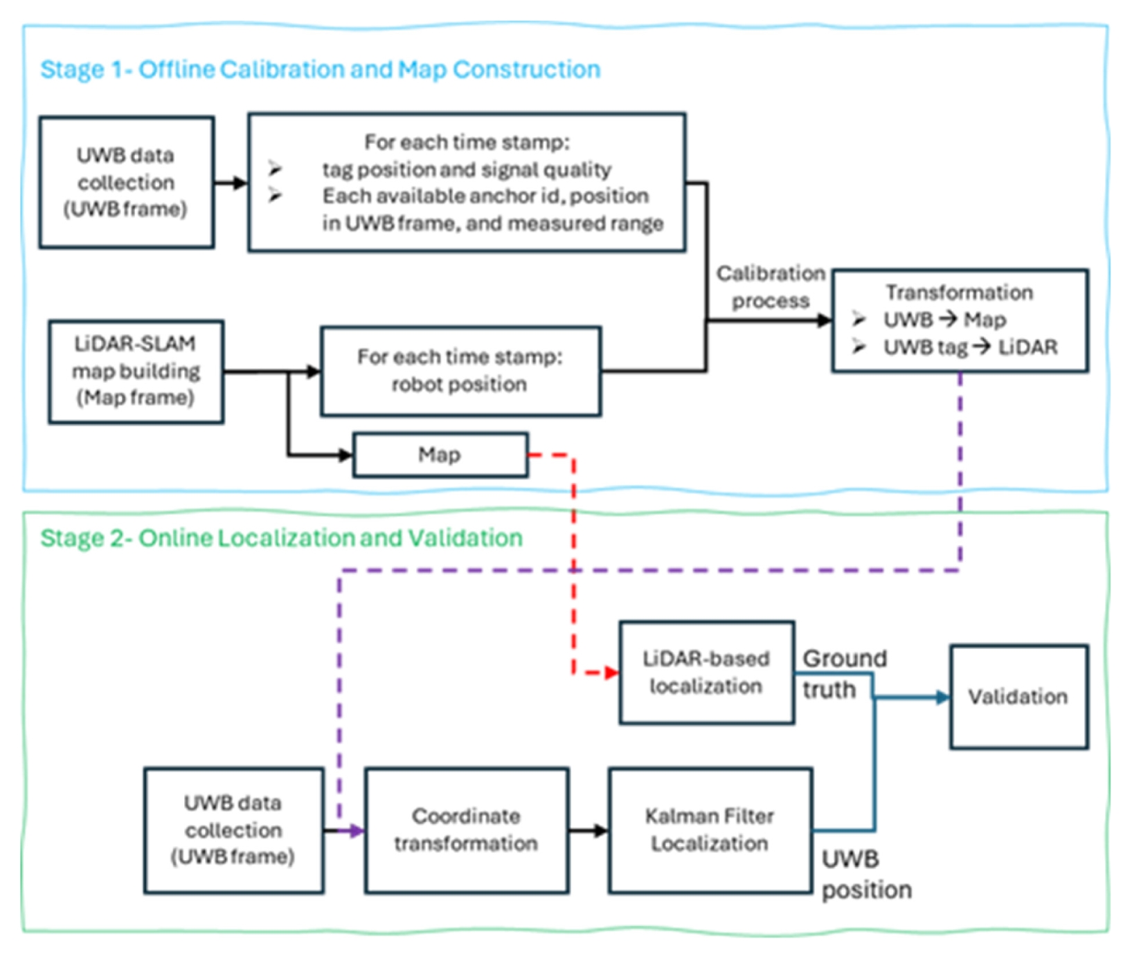
The proposed approach consists of two main stages: an offline calibration and validation stage, and an online localization demonstration stage, as shown in
Fig. 1.
In the offline stage, LiDAR-Inertial SLAM (DLIO) [
13] is used once to reconstruct the environment map and to collect synchronized pose and UWB range data. These data are used to calibrate the transformation between the LiDAR-SLAM map frame and the UWB anchor coordinate frame, as well as to generate a validation dataset for assessing the calibration accuracy.
In the online stage, the robot performs localization using raw UWB range measurements processed through a Kalman filter, where each estimated position is transformed into the pre-built LiDAR-SLAM map frame using the calibrated parameters. This experiment demonstrates the feasibility of using the calibrated UWB system for real-time localization within a pre-built map, without requiring continuous LiDAR or vision-based sensing.
2.2 UWB-LiDAR SLAM Calibration Procedure
The proposed calibration procedure estimates the rigid-body transformation between the UWB anchor frame and the LiDARSLAM map frame using only anchor-tag distance measurements. In contrast to conventional UWB network calibration methods that require anchor-anchor distances or full anchor geometry optimization [
12], our approach assumes that anchor positions are known in advance and fixed in the environment. This significantly simplifies the calibration process while maintaining reliable accuracy, provided that the UWB anchors are properly installed.
During the data-collection stage, the robot traverses the workspace while continuously recording synchronized LiDARSLAM poses and UWB ranges to each anchor. The calibration problem is then formulated as a nonlinear optimization that aligns the tag trajectory observed by LiDAR-SLAM with the UWB distance measurements.
This section describes the coordinate frames, measurement model, and optimization steps used to estimate the transformation between the LiDAR-SLAM map and the UWB anchor frame.
2.2.1 Coordinate Frames and Notation
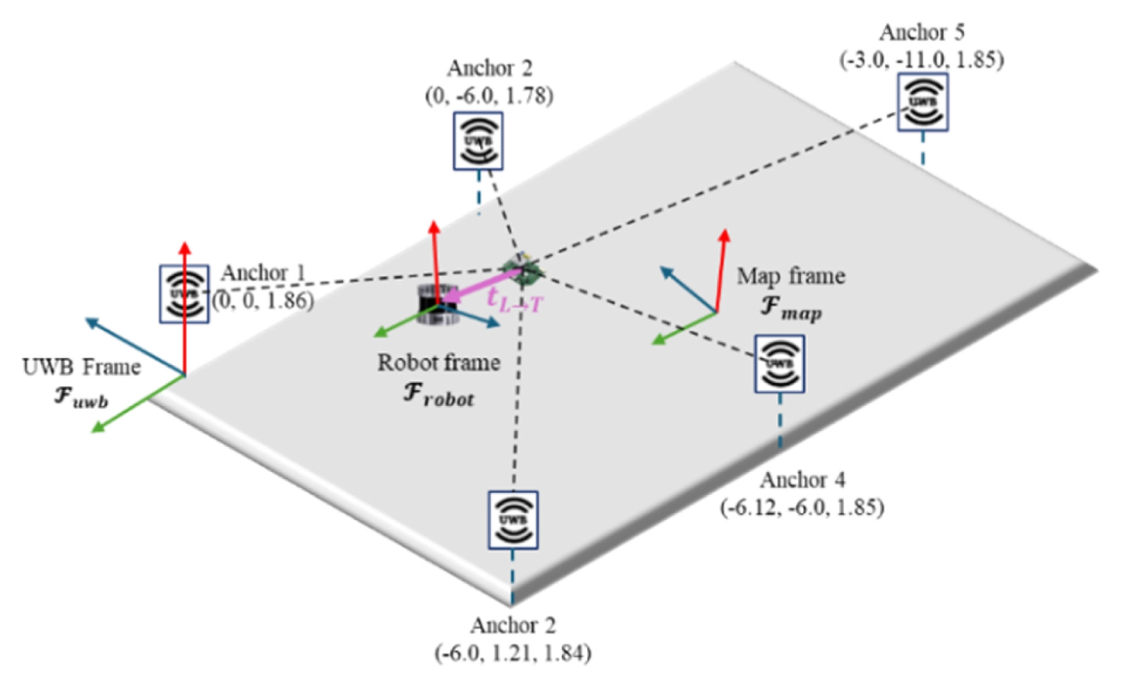
Three coordinate frames, as shown in
Fig. 2, are defined:
(1) LiDAR-SLAM map frame Fmap, which represents the global coordinate system obtained from the LiDAR-SLAM mapping stage.
(2) UWB anchor frame Fmap, defined by the fixed positions of the UWB anchors. Anchor i has known position:
(3) Robot frame Frobot, located at the LiDAR attached to the robot.
Because the UWB tag is physically offset from the LiDAR sensor, a fixed translation
is defined from the LiDAR frame to the UWB tag frame.
At timestamp k, the LiDAR-SLAM system provides the robot pose
The goal of calibration is to estimate the rigid transformation
mapping points from the UWB anchor frame to the SLAM map frame, where:
○ RUWB→map ∈ SO(3) is the rotation matrix and
○ tUWB→map ∈ ℝ3 is the translation vector.
2.2.2 Measurement Model Using Anchor-TAG Distance
The tag position expressed in map frame at timestamp k is:
The known anchor position in the UWB frame is transformed into the map frame as:
For each timestamp k, the UWB system measures the distance between anchor i and the tag:
where bi accounts for UWB bias. The bias term is introduced as a constant to account for systemic offsets, such as hardware delays and fixed multipath effects inherent to the anchor installation. While we utilize the Cauchy Loss Function during the offline optimization process to mitigate the impact of timevarying noise. The Cauchy function effectively down weights large residuals caused by temporary NLOS spikes or dynamic obstacles, allowing the algorithm to estimate a stable, rigidbody transformation even in the presence of transient noise. This ensures that the global coordinate alignment remains robust without the computational complexity of modeling bi for such a time-varying variable during the calibration phase, e.g. The residual for a given measurement is:
where mik is the anchor-tag measured range obtained from UWB. A key advantage of the proposed approach is that only anchor-tag distance measurements are required, no anchor-anchor distances or network self-calibration are needed. The only requirement is that anchor positions in UWB anchor frame Fuwb are known and fixed.
2.2.3 Optimization for Estimating Transformation
A practical advantage of the proposed calibration method is that it does not require using all anchors in the environment. Because the calibration relies solely on anchor-tag distance changes, a small subset of non-collinear anchors is sufficient to estimate the rigid transformation between the UWB and SLAM frames. In practice, three anchors form the minimum configuration for triangulation in 3D space, while using four anchors provides better geometric stability and improves robustness against temporary NLOS or biased measurements. Additional anchors beyond this subset can be incorporated during online localization without re-running the calibration process. Additionally, in UWB-systems, localization accuracy is highly sensitive to the precision of anchor coordinates. Traditional manual measurements of anchor positions are often prone to human error, which directly degrades navigation performance. To mitigate this, our proposed calibration method mathematically estimates the anchor position aiuwb obtained by manual measurement with additional biases bi. By using the highprecision trajectory from LiDAR-Inertial SLAM (DLIO) as a reference, we ensure that the UWB coordinate system is perfectly registered to the global map frame, minimizing the sensitivity issues typically found in manual configurations.
For compact notation, the following is defined:
● Rlidar,(k)map , plidar,(k)map : LiDAR-SLAM rotation and position at timestamp k
● Ruwb→map, tuwb→map : rotation and translation from UWB frame to map frame
● tL→T∈ℝ3 : translation from the LiDAR frame to the UWB tag frame
The predicted UWB distance at measurement(k, i) is:
Thus, the calibration residual is
Parameter Vector
The parameters to be optimized are:
Where (ϕUW, θUW, ψUW) denote roll-pitch-yaw of Ruwb→map, M is number of anchors.
Objective Function
Industrial environments are inherently dynamic, with human activity and moving equipment causing temporary Non-Line-of-Sight (NLOS) conditions. To ensure calibration remains accurate under these conditions, we employ a Cauchy loss function in our optimization pipeline. Unlike standard least-squares, the Cauchy function mathematically down weights data points with large residuals. This allows the algorithm to focus on stable Line-of-Sight (LOS) measurements while effectively ignoring the ‘noise’ or ‘spikes’ caused by human movement during the data collection phase.:
where
○ c is the Cauchy scale parameter and
○ K is the total number of measurements.
To ensure the reproducibility of our results, the specific hyperparameters used for the optimization and filtering stages are summarized in
Table 1. For the Cauchy loss function, the robustness constant was set to c = 0.4. This value was determined by analyzing the standard deviation of range measurements under Line-of-Sight (LOS) conditions, effectively treating larger deviations as outliers to ensure stable anchor coordinate estimation. The Particle Swarm Optimization (PSO) was configured with a population of 500 particles and a maximum of 100 iterations. To balance global exploration and local convergence, we utilized a linearly decreasing inertia weight ranging from
wmax = 0.9 to
wmin = 0.2. The acceleration coefficients were set to
c1 = 2 (cognitive component) and
c2 = 0.9 (social component). Additionally, the velocity was constrained within a range of 4% of the search space (
vmax = (upper bound - lower bound) * 0.04) to prevent divergence during the search process. Minimizing
J(θ) with Partial Swarm Optimization (PSO) yields the optimal rigid transformation between the UWB anchor frame and the LiDARSLAM map frame, as well as per-anchor bias terms.
After calibration (Section 2.2), the UWB module provides 2D position estimates in the map frame. These measurements contain noise and jitter due to multipath and partial NLOS conditions. Therefore, for real-time (online) localization, the transition from a static calibration to a dynamic environment is managed by a 2D constant-velocity Kalman filter. This filter accounts for the timevarying nature of UWB noise by smoothing measurement jitters and providing short-term trajectory predictions during brief signal dropouts. By combining the robust offline calibration parameters with this online filtering strategy, the system achieves a functional buffer against the dynamic interferences typical of cluttered offices.
State and Motion Model
The KF uses a 4-dimensional state:
with a standard constant-velocity transition model. The process noise covariance Q models small unobserved accelerations.
Measurement Model
The UWB system outputs a 2D position
which directly corresponds to the position components of the state. A linear observation model is used with measurement noise covariance R.
3. Experimental Setup and Validation
3.1 Experimental Setup
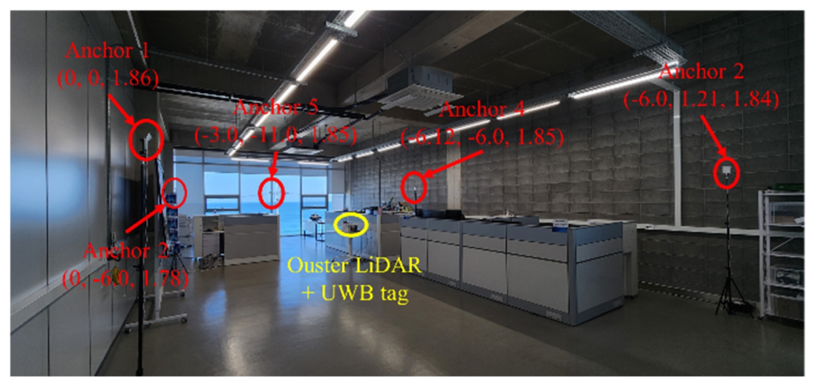
The calibration optimization was implemented in MATLAB and all other software components were implemented in the Robot Operating System (ROS) 2 Humble distribution running on Ubuntu 22.04. The experiments were conducted in an indoor office-like workspace (the presence of desks and cabinets effectively mimics the multipath and partial non-line-of-sight (NLOS) conditions found in cluttered industrial areas) with a total area of 7 m × 12 m and a ceiling height of 5 m. The UWB sensing system consisted of a Growspace Creator tag operating at 10 Hz and five fixed anchors installed around the perimeter at heights between 1.80 and 1.90 m, as shown in
Fig. 3. Because the UWB tag was mounted at a low height on the robot (approximately 0.45 m), nearby desks and cabinets acted as partial obstacles, frequently introducing multipath and partial non-line-of-sight (NLOS) conditions during the experiment.
For SLAM map construction, a high-resolution Ouster LiDAR was mounted at 1.20 m on the robot, and the DLIO LiDAR-Inertial SLAM (DLIO) algorithm [
13] was used to generate real-time SLAM poses and the global map. All data streams, including UWB ranges, SLAM poses, and LiDAR point clouds, were recorded in CSV format for offline calibration and evaluation.
Although five anchors were installed, only four were used during calibration, as the proposed method requires only a small subset of non-collinear anchors to estimate the UWB-SLAM transformation reliably. Additional anchors can be integrated during online localization without re-running the calibration.
3.2 Offline Validation
Offline validation was conducted to assess the accuracy of the proposed UWB-SLAM calibration procedure and the performance of the UWB-only localization with the proposed position-only Kalman filter.
3.2.1 Data Collection
The robot was manually driven through the environment while recording synchronized UWB-related data: tag position, UWB anchor-tag range measurements, anchor positions, LiDAR point clouds, and DLIO SLAM poses. Two datasets with different path shapes and anchor visibility conditions were collected. These datasets served as the basis for evaluating the calibration quality and for replaying UWB-only localization in the controlled offline environment where SLAM poses served as ground truth.
3.2.2 Calibration Evaluation
The calibration algorithm was executed offline using the recorded dataset and optimized using the PSO algorithm. To reduce the complexity of optimization problems. The calibration dataset was recorded with four anchors instead of 5. Therefore, we have 13 unknown variables (6 for UWB frame to world frame transformation, 3 for UWB tag to LiDAR translation, and 4 corresponding to each anchor biases) according to
Eq. (6). Additionally, we constrained the optimization variables based on physically measured distances in the environment, and the bias of each anchor was constrained to the interval -0.5 to 0.5 m.
To assess the calibration quality, anchor-tag distance residuals as computed before and after optimization. With a good variable upper and lower bound, the proposed method reduced the mean residual from 90 to 1.4 cm after 40 iterations, demonstrating the effectiveness of using anchor-tag distance measurements alone without requiring anchor-anchor constraints.
3.2.3 UWB-only Localization Replay
Using the calibrated transformation, each dataset was replayed to compute the UWB-only 2D trajectory. Position-only Kalman filter was applied to the UWB position output to obtain a smoothed estimate. The filtered trajectory was compared to the DLIO SLAM poses treated as ground truth.
3.3 Online Validation
Online validation was performed to confirm that the calibrated system can operate in real time without reliance in LiDAR data.
In the online experiment, the robot was driven inside the prebuilt map obtained by the offline calibration data collection stage. And the UWB tag provided 2D position estimates at 10 Hz. These positions were transformed into the map frame using the calibrated information obtained from offline calibration process Tuwb→map, and processed by the Kalman filter node.
4. Results and Discussion
4.1 Offline Results
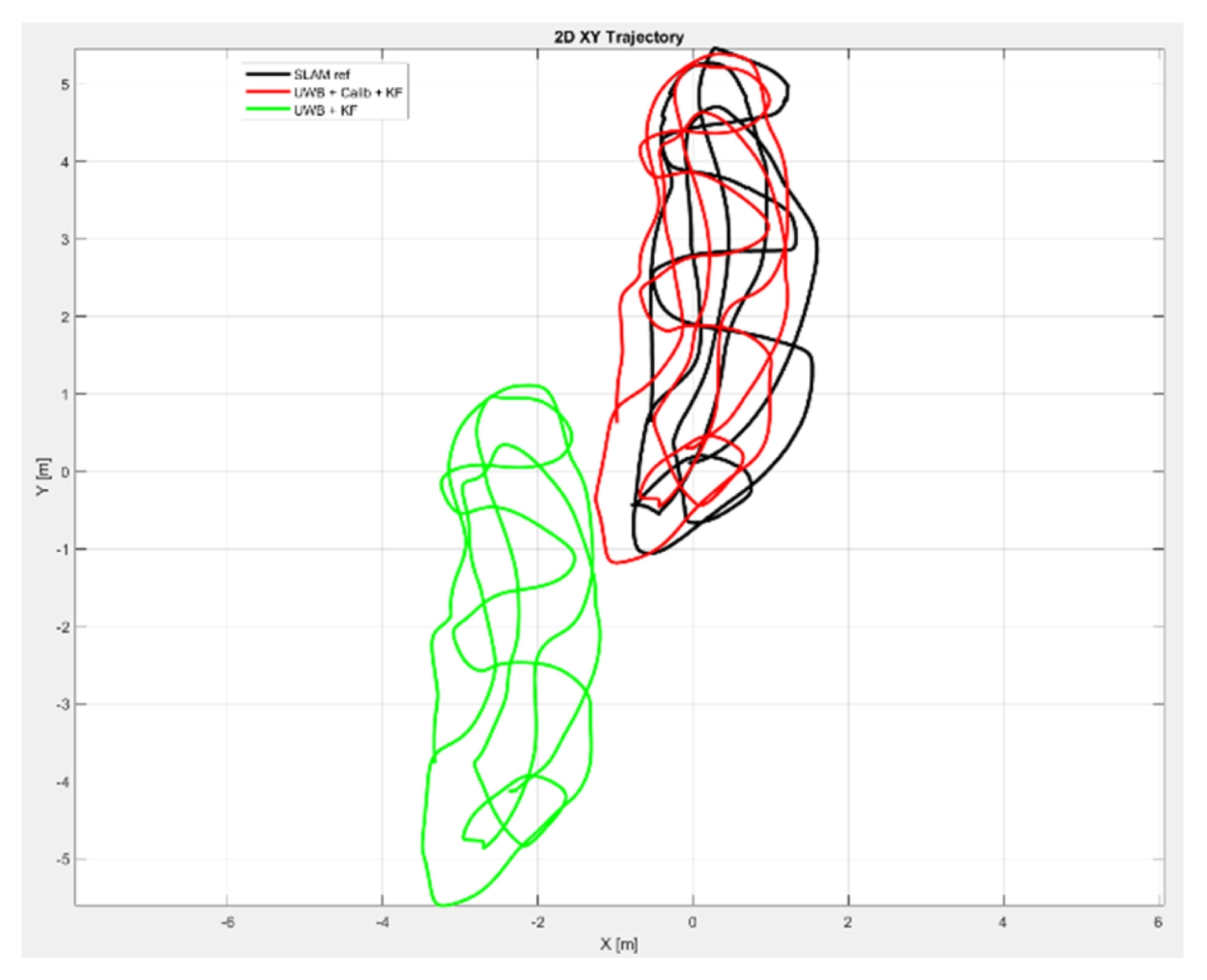
Fig. 4 presents a 2D trajectory comparison between SLAM reference and the UWB-based localization results. The raw UWB measurements, even after simple KF smoothing (green path), exhibit a significant global offset and drift due to the misalignment between the UWB and SLAM frames. After applying the proposed UWB-LiDAR calibration, the UWB trajectory (red path) aligns correctly with the SLAM trajectory (black path), and the KFsmoothed trajectory closely follows the reference path with significantly reduced jitter.
To quantify the improvement achieved by the proposed framework,
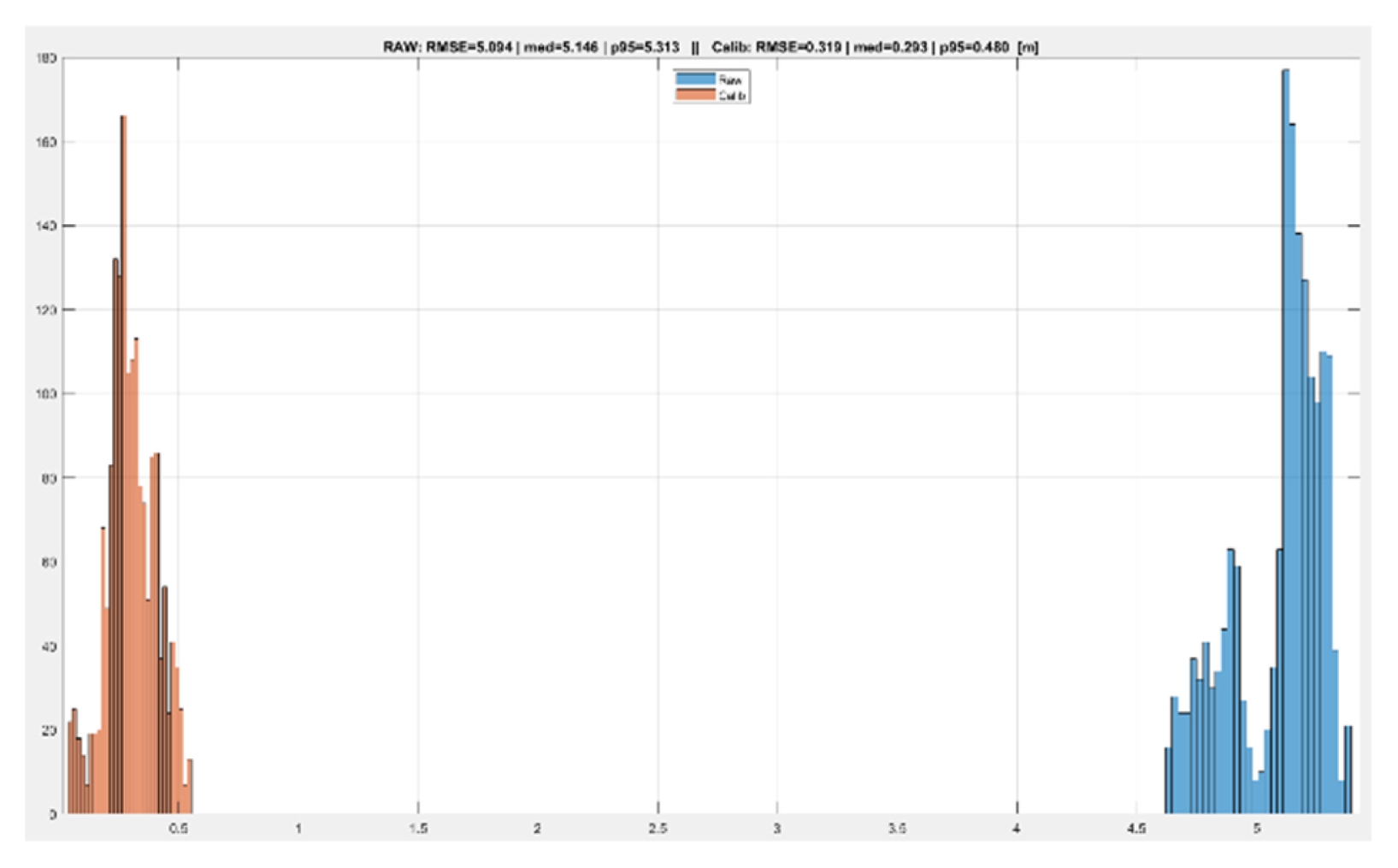
Fig. 5 illustrates the error distribution before and after calibration, with the specific numerical results summarized in
Table 2. The raw UWB output produced a large positional error (RMSE = 5.094 m), which would render autonomous navigation impossible. After calibration, the error dropped dramatically to an RMSE of 0.319 m. Notably, the 95th percentile error-which represents the system's reliability in worst-case scenarios-was reduced from 5.313 to 0.480 m. This substantial reduction confirms that the calibration step is essential for map-consistent localization.
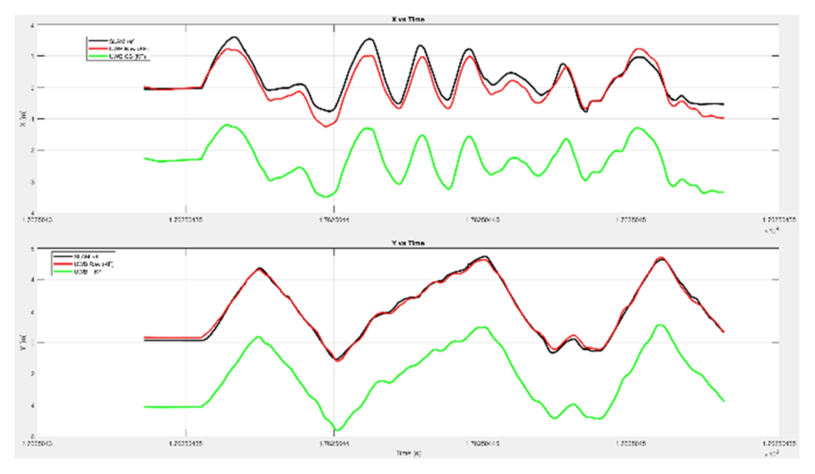
Fig. 6 presents the time-series comparison of the X and Y coordinates for the SLAM reference (black path), raw UWB + KF (green path), and calibrated UWB + KF (red path) trajectories. The calibrated + KF trajectory closely follows the SLAM reference across both axes, whereas the raw UWB output deviates significantly despite smoothing.
Although the X-axis shows larger oscillations than the Y-axis, we emphasize that this pattern reflects the inherent stochastic noise of the UWB sensor and the robot’s physical motion, rather than a deficiency in calibration accuracy. During the experiment, the robot moved predominantly along the X direction; thus, the high-frequency jitter characteristic of UWB radio signals in complex indoor workspaces becomes more visible along that axis of motion.
It is crucial to distinguish between systemic calibration accuracy (alignment to the map) and measurement variance (sensor jitter). Because the calibration parameters-anchor coordinates and systemic biases-were estimated and fixed during a separate offline phase, these online fluctuations do not influence the coordinate transformation's integrity. The Kalman Filter was intentionally tuned to maintain low-latency responsiveness; while it suppresses extreme outliers, it preserves enough bandwidth to track real-time steering adjustments, avoiding the 'lag' that would occur with oversmoothing. As the calibrated trajectory's mean position remains centered on the SLAM reference with a 94% error reduction, these observations confirm that the proposed framework provides a stable and accurate UWB-only localization solution suitable for real-time robotic navigation.
4.2 Online Results
To evaluate the real-time performance of the proposed UWBbased localization system, the calibrated transformation and the position-only Kalman filter were deployed as live ROS 2 nodes. During online operation, the robot moved autonomously inside the test environment while relying solely on UWB-based localization. The resulting trajectory was visualized in RViz together with the pre-built LiDAR-SLAM map.
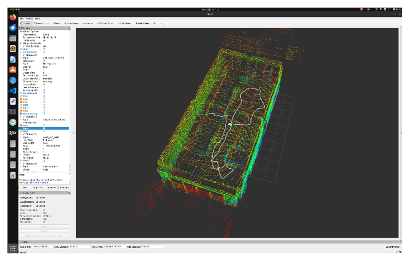
Fig. 7 shows the online localization output. The UWB-based trajectory (white curve) is projected onto the LiDAR-SLAM map generated in the offline stage. The trajectory follows a smooth and continuous path with no abrupt jumps, demonstrating that the position-only Kalman filter successfully suppresses measurement jitter and produces stable real-time localization. The robot’s motion is consistent with the expected path, and no significant drift or divergence was observed during the test sequence.
Because no LiDAR or odometry input was used during online evaluation, this result confirms that the calibrated transformation allows the UWB-derived positions to be directly interpreted in the global map frame. This enables operation in environments where LiDAR is unreliable or unavailable, such as dust-filled or occluded indoor areas. The RViz visualization confirms that the proposed UWB-only localization pipeline operates correctly in real time and provides map-consistent positioning suitable for navigation applications.
4.3 Discussion
The experimental results demonstrate that the proposed UWBSLAM calibration and UWB-only localization pipeline effectively removes the large global offset present in raw UWB positioning. By applying the rigid transformation, the absolute localization error was reduced from several meters to a map-consistent alignment. The position-only Kalman filter further stabilizes the trajectory by smoothing short-term noise and suppressing jitter caused by multipath and partial NLOS conditions typical of cluttered indoor workspaces.
The KF was intentionally tuned to maintain low-latency tracking, ensuring it smooths extreme outliers while preserving enough bandwidth to follow real-time robot maneuvers4. While a 2D localization model was used, the framework inherently leverages 3D LiDAR-Inertial SLAM during the offline calibration phase, storing anchor positions as 3D coordinates (aimap). This 3D-aware foundation ensures the core methodology is fully compatible with future 3D state estimation in sloped or multi-level environments.
This preliminary feasibility study confirms the system produces a stable, globally consistent pose estimate. Although testing was conducted in an office-like environment, the resulting RMSE of 0.319 m demonstrates basic technical verification of the algorithm against environmental noise. The integration of the Cauchy loss function and Kalman filter resulted in a 94% reduction in positional error, proving the initial viability of a UWB-only approach. Future research will build upon this verification by exploring machine learning-based noise prediction and 6-DOF sensor fusion in dense, large-scale industrial facilities.
4.4 Practical Utility and Feasibility Analysis
While the post-calibration RMSE remains at 0.319 m, this level of accuracy provides sufficient precision for "navigation-grade" global positioning within indoor maps. In typical autonomous mobile robot (AMR) workflows, localization is hierarchical: UWB establishes the global pose required to reach a target vicinity, while secondary precision sensors facilitate high-accuracy tasks like docking. An error margin of approximately 30 cm falls within the operational tolerance for initiating such local maneuvers.
This study specifically addresses the vulnerability of feature-based SLAM in challenging perception zones. By using SLAM strictly as an offline calibration tool, the robot “inherits” a precise coordinate frame without requiring the continuous availability of LiDAR features. This “one-time calibration” approach establishes a verified foundation for environment-independent localization. As a feasibility study, these results confirm that the proposed pipeline is a robust fail-safe for maintaining map-consistent trajectories, laying the groundwork for subsequent deployment in future factory automation settings.
FOOTNOTES
-
ACKNOWLEDGEMENT
This work was supported by 2024 Shipbuilding and Maritime Development Project (No. RS-2024-00431759, Development of Automation Technology for Over 50% Improvement in Blasting Speeds of Pre-erection Process of Inner and Outer Hull Blocks) funded By the Ministry of Trade, Industry and Energy (MOTIE, Korea).
Fig. 1Workflow of the proposed two-stage UWB-LiDAR SLAM localization framework. Stage 1 performs LiDAR-SLAM mapping and calibration using anchor-tag distance data to compute the transformation between the UWB anchor frame and the LiDAR-SLAM map frame. Stage 2 applies a Kalman filter to raw UWB range data for real-time localization, transforms the estimates into the pre-built map frame using the calibrated parameters, and validates the results against LiDAR-SLAM ground truth
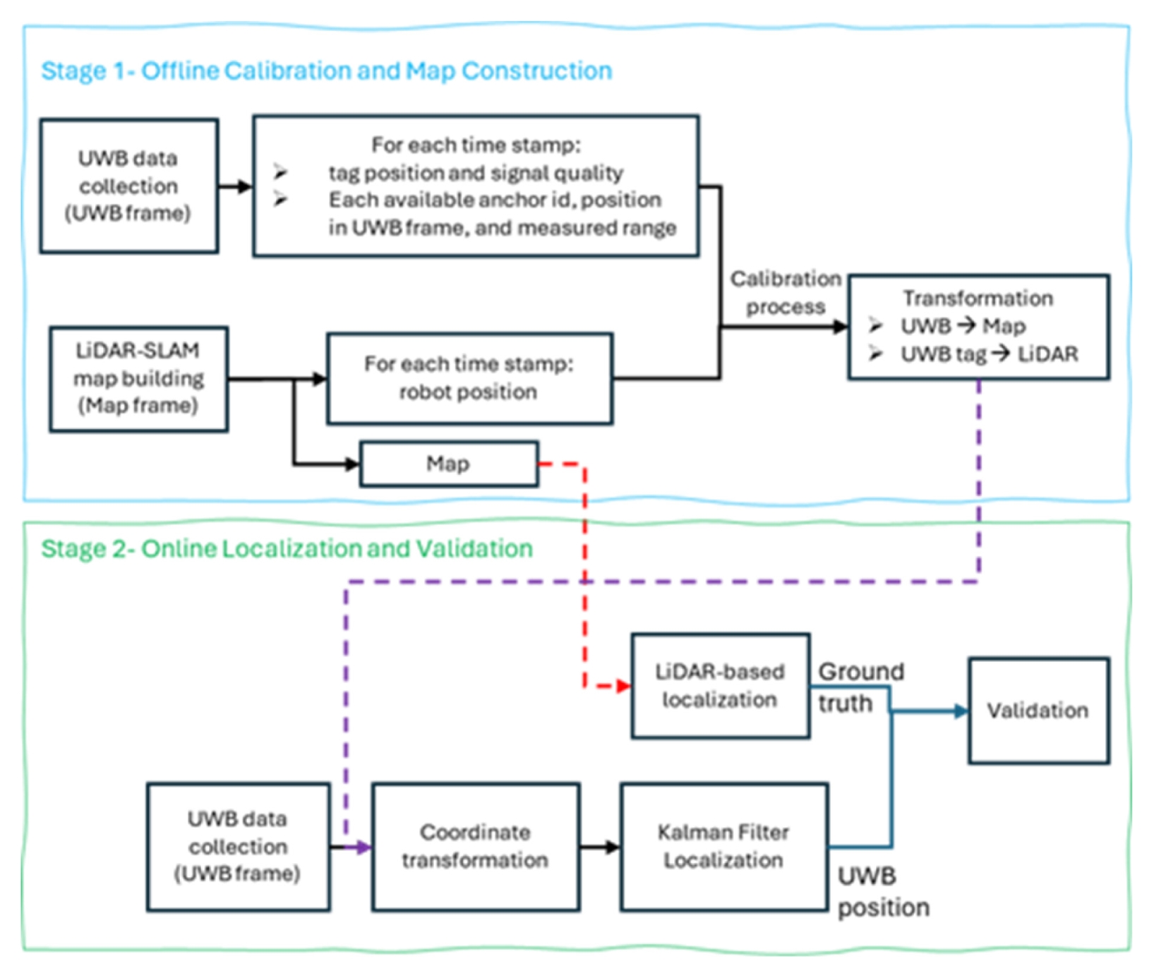
Fig. 2Coordinate frames and anchor configuration used for UWBLiDAR calibration and validation
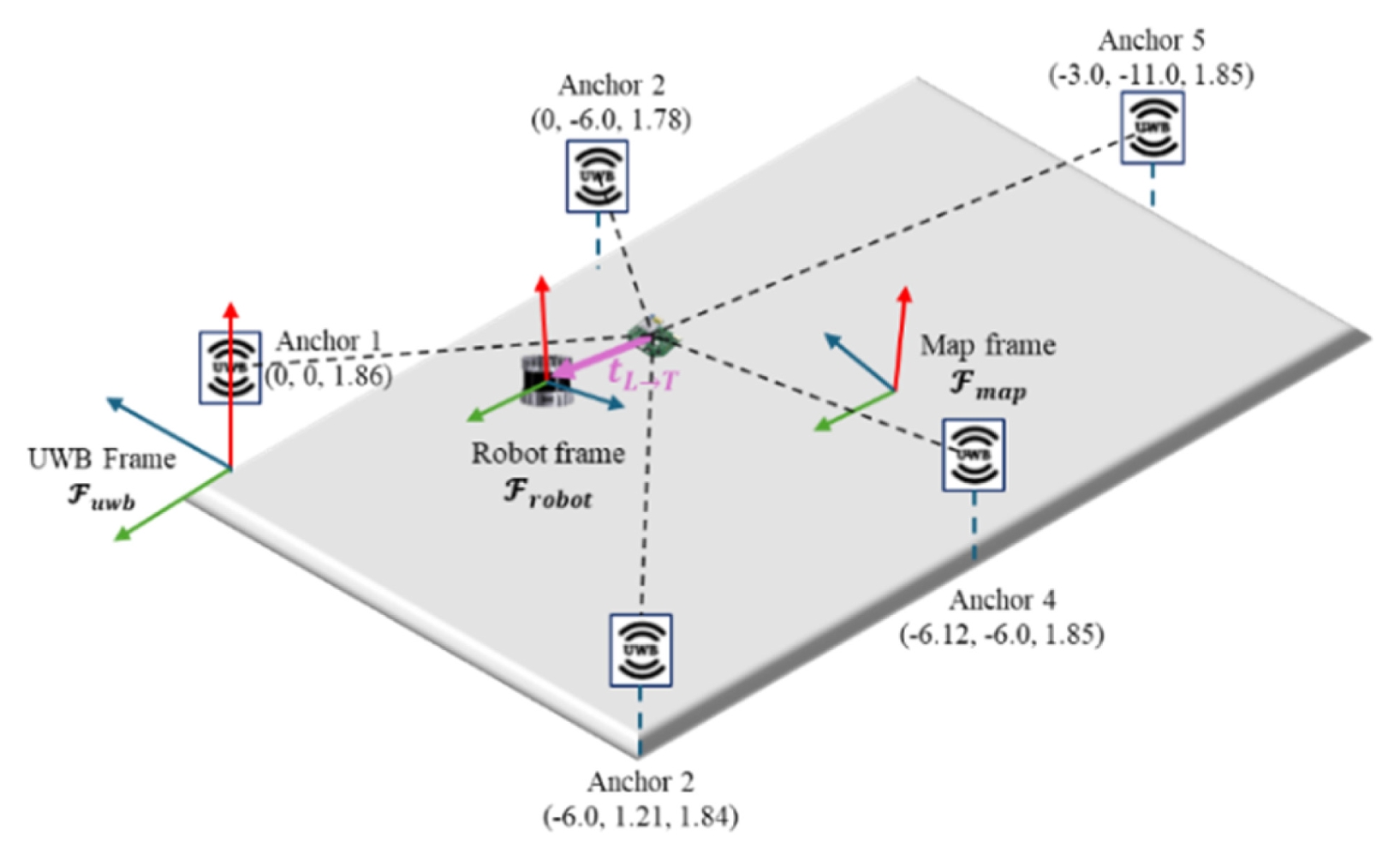
Fig. 3
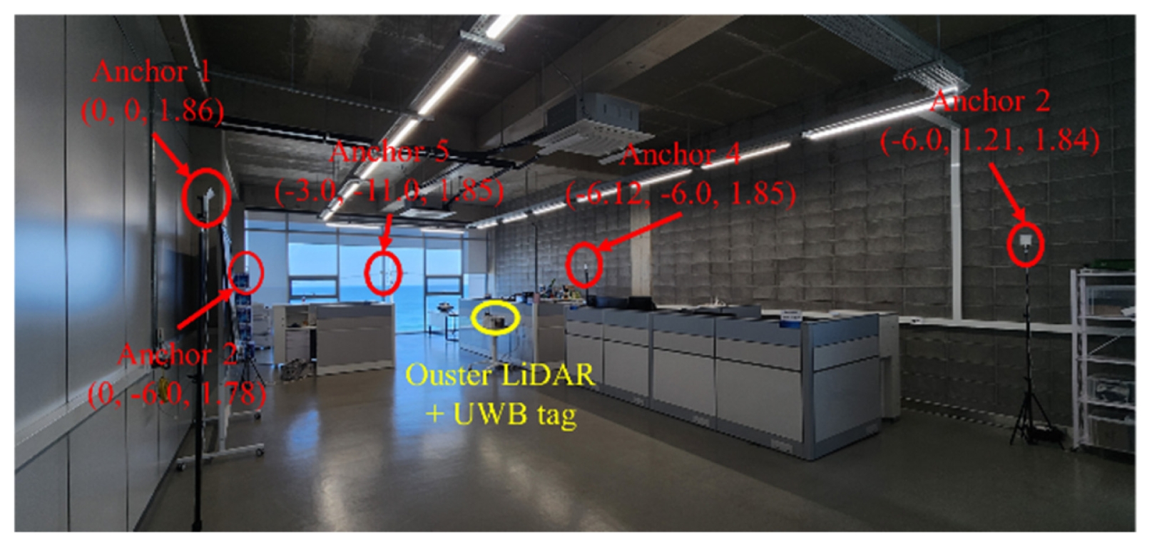
Fig. 4Comparison of 2D trajectories: SLAM reference, raw UWB (KF), and calibrated UWB (KF)
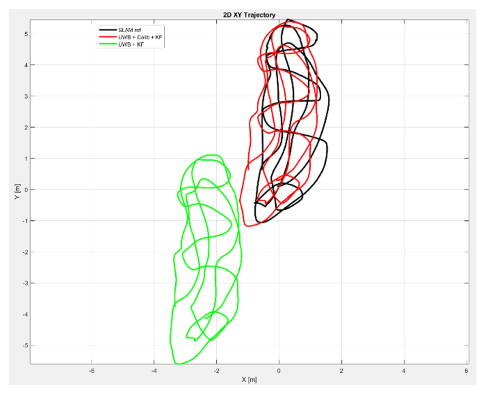
Fig. 5Histogram of localization errors before and after calibration
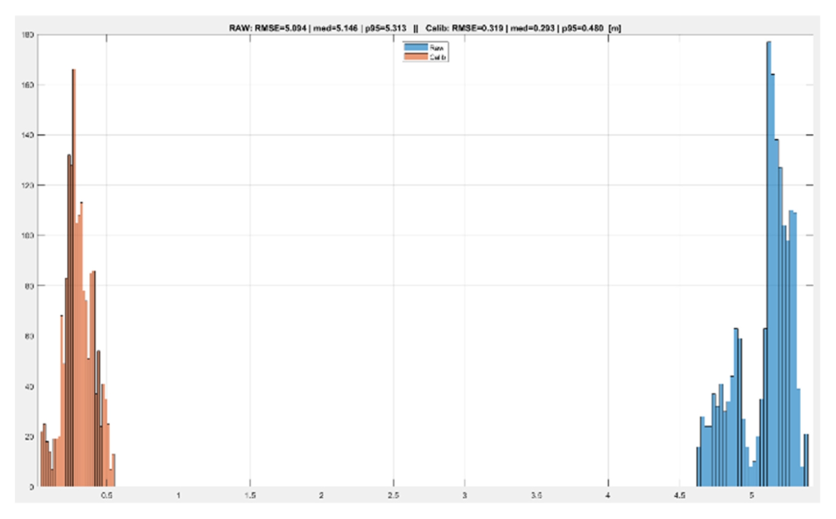
Fig. 6Time-series comparison of X and Y coordinates for SLAM reference, raw UWB (KF), and calibrated UWB (KF)
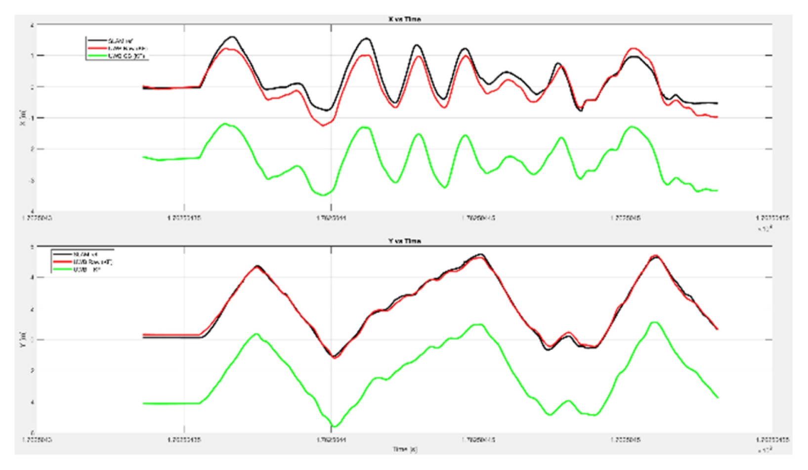
Fig. 7Online UWB-only localization visualized in RViz2 over the pre-built LiDAR-SLAM map
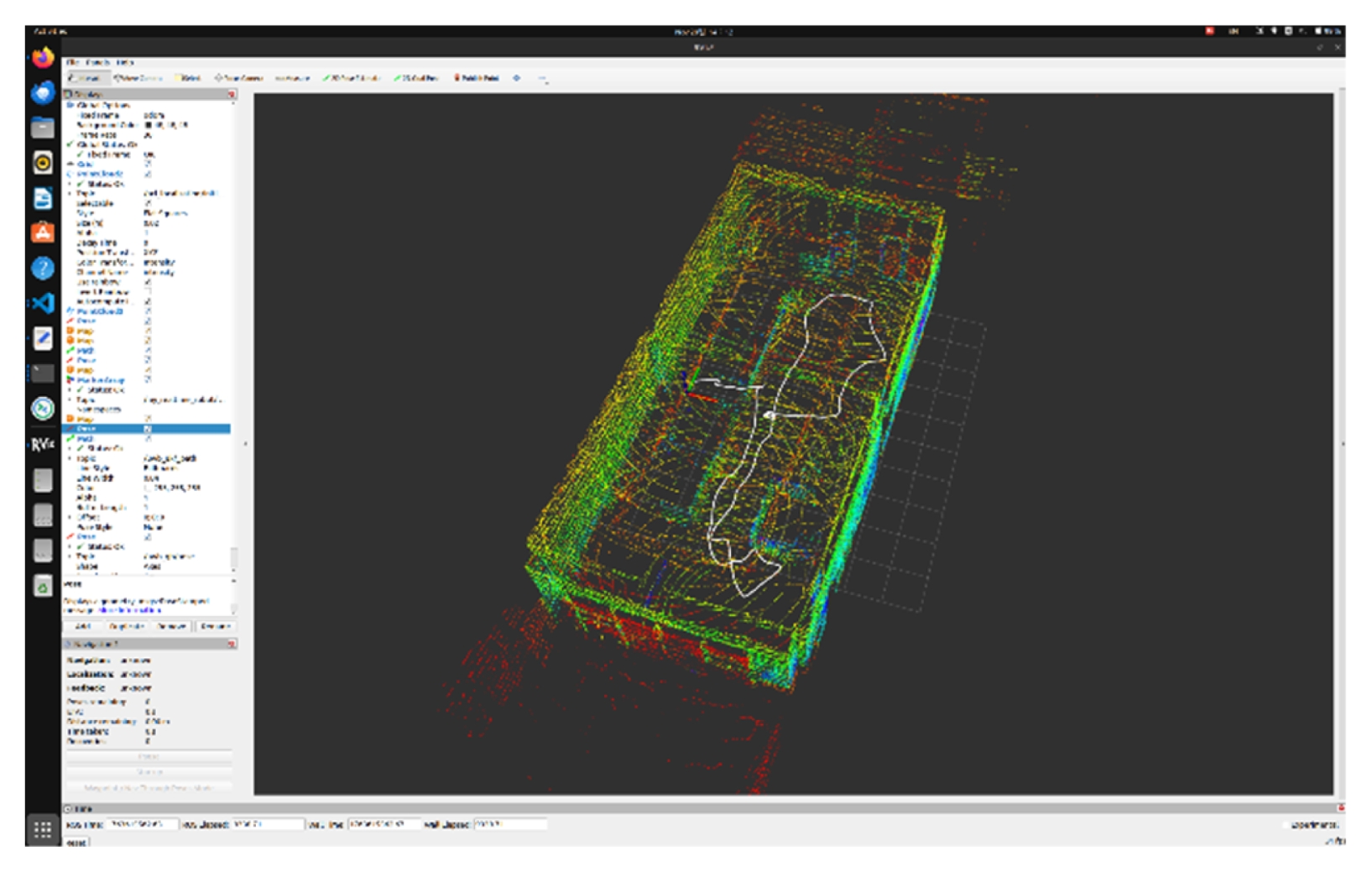
Table 1Configuration of PSO hyper-parameters and Cauchy cost function
Table 1
|
Category |
Parameter |
Value |
|
Cauchy loss |
Robustness constant (c) |
0.4 |
|
PSO |
Swarm size (Particles) |
500 |
|
Max iterations |
100 |
|
Inertia weight (w) |
0.9 → 0.2 (linear decay) |
|
Acceleration (c1, c2 ) |
2.0, 0.9 |
|
Velocity limit (v max ) |
4% of search space |
Table 2Quantitative comparison of localization performance before and after calibration
Table 2
|
Metric Raw |
UWB + KF |
Proposed |
Improvement |
|
RMSE [m] |
5.094 |
0.319 |
93.70% |
|
Median error [m] |
5.146 |
0.293 |
94.30% |
|
95th percentile [m] |
5.313 |
0.48 |
90.90% |
|
Max error [m] |
5.62 |
0.71 |
87.30% |
REFERENCES
- 1. Van Herbruggen, B., Luchie, S., Fontaine, J., De Poorter, E., (2023), Multihop self-calibration algorithm for ultra-wideband (uwb) anchor node positioning, IEEE Journal of Indoor and Seamless Positioning and Navigation, 1, 1-11.
- 2. Chwełatiuk, K., Kubina, A., Michalak, M., Sikora, M., Ściegienka, P., Wróbel, Ł, (2025), Algorithm for determining the position of a ship hull-cleaning robot, Applied Sciences, 15(10), 5705.
- 3. Wang, S., Ahmad, N. S., (2024), Robust classification of uwb NLOS/LOS using combined FCE and XGBoost algorithms, IEEE Access, 12, 151030-151045.
- 4. Sang, C. L., Steinhagen, B., Homburg, J. D., Adams, M., Hesse, M., Rückert, U., (2020), Identification of NLOS and multi-path conditions in UWB localization using machine learning methods, Applied Sciences, 10(11), 3980.
- 5. Zhao, M., Chang, T., Arun, A., Ayyalasomayajula, R., Zhang, C., Bharadia, D., (2021), Uloc: Low-power, scalable and cm-accurate UWB-Tag localization and tracking for indoor applications, Proceedings of the ACM on Interactive, Mobile, Wearable and Ubiquitous Technologies, 5(3), 1-31.
- 6. Mazhar, F., Khan, M. G., Sällberg, B., (2017), Precise indoor positioning using UWB: A review of methods, algorithms and implementations, Wireless Personal Communications, 97(3), 4467-4491.
- 7. Minoli, D., Occhiogrosso, B., (2018), Ultrawideband (UWB) technology for smart cities IOT applications, Proceedings of the IEEE International Smart Cities Conference (ISC2), 1-8.
- 8. Shule, W., Almansa, C. M., Queralta, J. P., Zou, Z., Westerlund, T., (2020), UWB-based localization for multi-UAV systems and collaborative heterogeneous multi-robot systems, Procedia Computer Science, 175, 357-364.
- 9. Ridolfi, M., Kaya, A., Berkvens, R., Weyn, M., Joseph, W., Poorter, E. D., (2021), Self-calibration and collaborative localization for UWB positioning systems: A survey and future research directions, ACM Computing Surveys, 54(4), 1-27.
- 10. Feng, D., Wang, C., He, C., Zhuang, Y., Xia, X.-G., (2020), Kalman-filter-based integration of imu and UWB for high-accuracy indoor positioning and navigation, IEEE Internet of Things Journal, 7(4), 3133-3146.
- 11. Wei, M., Liu, L., Li, S., Wang, D., Li, W., (2025), Gauss-AUKF based UWB/IMU fusion localization approach, Ad Hoc Networks, 175, 103855.
- 12. Nguyen, T.-D., Nguyen, T.-M., Nguyen, V.-H., (2025), Coordinate-consistent localization via continuous-time calibration and fusion of UWB and SLAM observations, Proceedings of the International Symposium on Electrical and Electronics Engineering, 107-112.
- 13. Chen, K., Nemiroff, R., Lopez, B. T., (2022), Direct lidar-inertial odometry: Lightweight LIO with continuous-time motion correction, arXiv preprint arXiv:2203.03749.
- 14. Chen, Z., Xu, A., Sui, X., Wang, C., Wang, S., Gao, J., Shi, Z., (2022), Improved-UWB/LiDAR-SLAM tightly coupled positioning system with nlos identification using a LiDAR point cloud in GNSS-denied environments, Remote Sensing, 14(6), 1380.
Biography
- Van-Tung Ha
Postdoctoral Researcher with the Korea Institute of Robotics and Technology Convergence (KIRO), South Korea. His research interests include three-dimensional (3D) scanning technology, computer vision, simultaneous localization and mapping (SLAM), robot localization and visionbased robotic systems.
- Myeongsu Jeong
He is a Team Leader and Principal Researcher with the Manufacturing AX Robotics Research Group / Manufacturing Humanoid Integration Research Team, Korea Institute of Robotics & Technology Convergence (KIRO), South Korea. His research interests include real-time high-speed motor control, sensor fusion, embedded intelligence systems, and system architecture design and firmware development for humanoid robotic platforms.
- Song Eun Park
Researcher at the Integrated Robotics Systems Research Division, Korea Institute of Robotics & Technology Convergence (KIRO), Republic of Korea. His research interest is mobile robot.
- HyungJun Kim
Researcher with the Korea Institute of Robotics and Technology Convergence (KIRO), South Korea. His research interests include robotic system integration, embedded firmware, and application-level software development.
- Jonghwan Baek
Senior researcher with the Korea Institute of Robotics and Technology Convergence (KIRO), South Korea. His research interests include robot vision-based robotic systems, signal processing and system control.
- Jaeyoul Lee
He is currently serving as the Head and Chief Researcher of the Manufacturing AX Robotics Research Group at the Korea Institute of Robotics and Technology Convergence (KIRO). His current research interests include humanoid systems, AX conversion research for humanoid utilization tasks that transfers human expertise to robots.