ABSTRACT
In the rapidly evolving e-commerce industry, high-quality and consistent product images are essential for engaging consumers. Traditional manual photography often lacks consistency, while advanced robotic solutions can be overly complex and expensive for standardized cataloging. This paper details the design and validation of a 4-DOF (Degrees of Freedom) automated system for standardized product photography. The system employs a modular, fixed-platform architecture that adjusts camera height, tilt angle, object rotation, and perspective translation. An integrated control system facilitates automatic pose planning based on object size, ensuring efficient operation. We quantitatively evaluated the system's performance using metrics for perspective consistency and repeatability. Experimental results across various product types showed high stability, with minimal variance in bounding box area ratios from different viewpoints. The system exhibited exceptional repeatability in random trials, consistently achieving pair Intersection over Union (IoU) values above 0.90. This high level of geometric precision confirms the system's reliability for capturing uniform, multi-angle product images. Ultimately, this capability allows for the scalable and automated production of high-quality visuals for e-commerce.
-
KEYWORDS: Photography, Automation robot, Commerce, Robotic system
-
KEYWORDS: 사진촬영, 자동화 로봇, 상거래, 로봇 시스템
1. Introduction
With the rapid expansion of the e-commerce industry, highquality and standardized product images have appeared as one of the most decisive factors influencing consumer engagement and conversion rates. It is well established that in e-commerce, visual presentation is predominant. Prior research has consistently shown that elements such as background arrangement, contrast levels, and the overall visual complexity of an image play a significant role in attracting consumer attention and influencing purchasing behavior [
1]. In the realm of marketing psychology, studies indicate that the angle at which a product is photographed can drastically alter how it is perceived, affecting its perceived quality and appeal [
2]. Furthermore, visual factors like brightness and color coordination have been found to have a direct impact on click-through rates [
3]. Together, these insights emphasize that capturing consistent, multi-perspective images is not just a technical necessity but a fundamental strategy that can drive commercial success in online marketplaces. These days, solutions for achieving this consistency are often misaligned with the needs of online retail. So, conventional product photography continues to demand manual DSLR setups or complex, multidegrees of freedom robotic arms which is built for generalpurpose imaging. Advanced technologies such as viewpoint tracking or automated pose optimization have shown reasonable, but they are often too sophisticated and expensive for mainstream e-commerce product categories like shoes, cosmetics, and accessories [
4,
5]. These systems are designed with specialized use cases in mind, which makes them impractical for large-scale catalog production due to their high costs, complex mechanics, and the ongoing maintenance they require. On the other hand, traditional photography methods are often inconsistent, as photographer's skill, fatigue, and subjective judgment can lead to discrepancies in image quality [
6-
8]. This often results in costly post-processing and the need for retakes. While early studies about robotic photography suggested automation's potential, as these efforts mainly focused on human subjects or dynamic settings, not the repetitive, structured nature of product photography [
6,
8-
11]. More recent attempts to develop portable, lower-cost systems have focused on areas like agriculture [
12] or prioritized flexibility for dynamic environments [
4,
13,
14]. However, they have not been designed to meet the specific requirements of e-commerce product imaging, especially for consistent, multi-angle views. Additionally, simple solutions like optimized lightboxes [
15-
20] improve image quality but still rely on manual adjustments and interference, showing the persistent need for human participation in the process. So, a gap remains for a fixed-platform, cost-effective, and automated photographing system explicitly customized for standardized product categories.
This research presents a portable imaging robot designed to address the challenge of capturing consistent, multi-angle photographs of standardized products such as shoes and cosmetics. The system utilizes a modular design with four degrees of freedom (camera height, tilt, translation, and object rotation), controlled by a coordinated motor system that adjusts the camera's position according to the size of the photographed object. We evaluated the system’s performance through strict testing, confirming its ability to deliver consistent and repeatable results. The paper is organized as follows: Section II covers the system's design and architecture, Section III presents the experimental results and evaluation of results, and Section IV discusses the findings, limitations, and potential future improvements.
2. Design and Fabrication, Integration of the Proposed Camera Robot
This section shows the overall design and fabrication of the proposed robotic system, as well as the definition of capturable objects and the robot's workspace.
2.1 System Design and Fabrication
The robotic system, as presented in
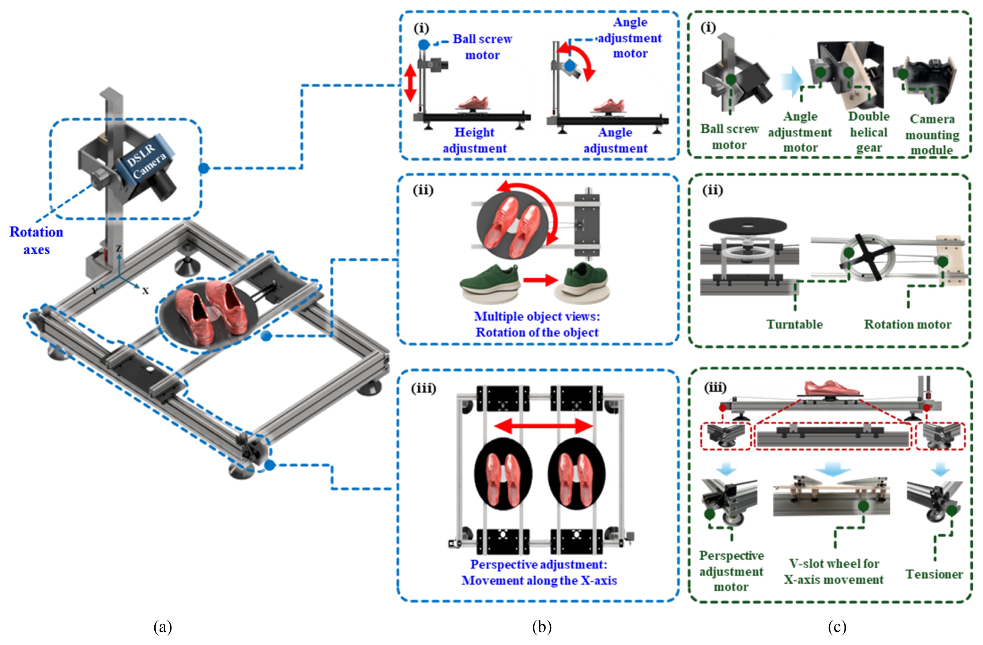
Fig. 1, consists of three modular components to enable flexible multi-angle product photography. The overall frame was constructed with 3060 aluminum profiles to ensure structural rigidity and modularity, while the object support part was fabricated with 2020 aluminum profiles.
Fig. 1(a) illustrates the overall design of the proposed robotic system. As shown in the system design, linear motions are composed of the object's translation along the X-axis and the camera's translation along the Z-axis. The camera posture module (
Fig. 1(b-i)) adjusts the camera height along the Z-axis by a linear ball screw motor and controls the tilt angle using an Angle adjustment motor. The object rotation module (
Fig. 1(b-ii)) rotates the object to presents images from multiple viewpoints. The perspective adjustment module (
Fig. 1(b-iii)) manipulates the object's X-axis position to transform the relative viewpoint between the camera and the object. These modules operate cooperatively to achieve precise control of relative positions of the camera and the object. Once the object size and desired angle are specified, the system automatically performs camera adjustment, object translation, and rotation. This modular structure provides flexibility across different object dimensions and ensures strong consistency and repeat ability in operation. From a system-level design perspective, the proposed robotic system was intentionally configured with four degrees of freedom (4-DOF), consisting of object translation, camera translation, object rotation, and camera tilt. This configuration was selected to focus on task-critical motions required for general product photography while avoiding unnecessary mechanical complexity associated with higher-degreeof-freedom robotic systems.
The fabricated prototype is shown in
Fig. 1(c). To build the robotic system, we selected a combination of off-the-shelf mechanical parts and custom 3D-printed components which not only simplified maintenance using readily available hardware but also enhanced the overall production process by improving efficiency through additive manufacturing. In particular, the component design and selection criteria emphasize modularity and user-level customization, allowing individual modules to be easily modified, replaced, or extended according to specific application requirements. The camera positioning module (
Fig. 1(c-i)) is powered by a low-friction, quiet LSM4-NK235630 linear ballscrew motor, ensuring stable and smooth vertical movement of the camera. The camera is mounted securely on a dedicated bracket, the Canon EOS R7 is supported by a double-helical gear system that ensures precise, backlash-free tilt adjustments. For rotating the object (
Fig. 1(c-ii)), we selected a turntable powered by a stepper motor coupled with a timing belt, enabling full 360-degree rotation. A ball-bearing support structure stabilizes the system, minimizing friction and ensuring stable, precise rotation under various products. The module that adjusts the object's perspective (
Fig. 1(c-iii)) moves along the X-axis via a motorized pulley and belt system, with V-slot wheels and a belt tensioner working together to ensure consistent, repeatable positioning. These individual modules were first fabricated separately and then assembled into the final system, allowing for easy maintenance, upgrades, and scalability without requiring complete disassembly.
In this study, a workspace analysis was conducted to quantitatively define the feasible object size range that can be stably photographed by the proposed automated imaging system. Considering portability and installation constraints, the maximum horizontal translation range of the object was set to 700 mm, and the camera height was designed to be adjustable to 500 mm. The imaging system employs a Canon EOS R7 camera equipped with an RF35 mm F1.8 MACRO IS STM lens. Since both object height and camera tilt angle simultaneously influence the visible region during photography, the workspace analysis was performed based on a two-dimensional side-view cross section of the robot–object–camera system. The three-dimensional geometry of an object was represented by its cross-sectional envelope in the side view, and feasibility was evaluated by determining whether this envelope was fully contained within the camera field of view (FOV).
2.2.1 Camera Field-of-view Model
Based on the lens specifications, the horizontal field of view (HFOV) of the camera was calculated as:
where d denotes the horizontal size of the image sensor (22.3 mm) and f is the focal length of the lens (35 mm). This yields a horizontal FOV of approximately 35.3°. The vertical FOV was derived from the sensor aspect ratio. At a camera–object distance Z, the physical coverage of the camera FOV can be expressed using basic triangular geometry as
where W(Z) and H(Z) represent the horizontal and vertical extents of the visible region, respectively.
2.2.2 Maximum Object Size Determination
The maximum allowable object size was defined as the intersection of feasible object sizes across all photographing configurations, including frontal, tilted, and top-down views. Among these configurations, the most restrictive condition determines the upper bound of the feasible workspace. In the frontal and tilted views, the camera–object distance can be increased to accommodate larger objects within the FOV. In contrast, during the top-down view, the camera height is limited to a maximum of 500 mm, preventing further expansion of the visible region. Consequently, the top-down configuration imposes the most stringent geometric constraint and governs the maximum allowable object size for the entire system.
Accordingly, the maximum object size was defined based on the top-down view. To ensure framing robustness under real operating conditions, a margin factor p was introduced. This factor accounts for practical non-idealities such as lens distortion, camera mounting inaccuracies, and object placement errors by restricting the usable region to the central effective area of the FOV. In this study, a conservative value of p = 0.9 was adopted.
The maximum allowable cross-sectional envelope is thus given by:
where Zminrobot 500 denotes the maximum camera height in the top-down configuration. Substituting the system parameters yields a maximum allowable object size of approximately 287 × 190 mm, which is satisfied across all photographing configurations. This value is therefore defined as the upper bound of the feasible object size range.
2.2.3 Minimum Object Size Determination
The minimum object size was defined to ensure the reliability of the quantitative evaluation metrics used in the repeated photographing experiments, namely the Intersection over Union (IoU) and the perceptual stability index (PSI). In this study, object bounding boxes were automatically extracted using Python-based image processing algorithms. As a result, pixel-level boundary fluctuations caused by illumination variation, thresholding, and quantization are unavoidable. If the object size is too small, such pixel-level boundary errors occupy a relatively large proportion of the bounding box, leading to increased variability in IoU and PSI that is unrelated to the mechanical repeatability of the system. To mitigate this effect, a minimum bounding-box dimension of Nmin pixels was imposed in both horizontal and vertical directions in the side-view cross section.
At a camera–object distance Z, the physical length corresponding to a single pixel can be expressed as:
where θ is the FOV in the corresponding direction and N is the image resolution. Accordingly, the minimum object size under the most unfavorable condition, the maximum effective viewing distance Zmax is defined as:
In this study, Nmin = 200 pixels were selected, and the maximum effective distance was calculated as Zmax ≈ 860 mm. With image resolutions of Nh = 6,960 and Nv = 4,640, the minimum object size was determined to be approximately 16 × 16 mm in terms of the side-view cross-sectional envelope. This value was adopted as the minimum object size that enables stable framing and reliable quantitative evaluation.
2.2.4 Feasible Object Size Range
Based on the above analysis, the feasible object size range of the proposed system, defined in terms of the side-view cross-sectional envelope, can be summarized as
This range represents a conservative design criterion that simultaneously satisfies camera FOV constraints, robotic motion limits, and the stability requirements of image-based evaluation metrics.
2.2.5 Selection of Representative Objects and Viewing Angles
Based on the feasible object size range derived above, representative products were selected to validate the proposed system. Cosmetics, pouches, and shoes were chosen as target objects, as they are among the most frequently traded items in e-commerce platforms and exhibit diverse geometric characteristics. The dimensions of each product category were determined according to typical aspect ratios observed in commercial products: 1 : 1 : 3 for cosmetics, 4 : 1 : 3 for pouches, and 0.8 : 2.5 : 1 for shoes. All selected objects fall within the feasible size range defined in Section 2.2, ensuring compatibility with the geometric and kinematic constraints of the proposed system.
The camera tilt angles of 0, 45, and 90° were selected as representative viewpoints commonly used in commercial product photography, while minimizing redundancy. The 0° configuration corresponds to a frontal view typically used as the primary product image. The 45° configuration provides an oblique view that enhances depth perception and geometric features and is widely adopted in online product listings. The 90° configuration captures either a top-down or side-profile view, depending on the product type, and is commonly used to present overall shape or layout information. Together, these three configurations form a compact yet representative set of viewpoints that sufficiently cover practical photographing requirements.
For cosmetics and pouches, frontal views were considered at tilt angles of 0 and 45, while at 90° the objects were assumed to be laid flat on the platform, reflecting common photographing practices. For shoes, frontal views were also considered at 0 and 45, whereas at 90° the shoes were rotated by 90° to capture a sideprofile view.
2.2.6 Simulation Procedure and Geometric Evaluation
For each tilt angle, the camera height varied from 0 to 500 mm in increments of 50 mm, resulting in 11 discrete simulation points per angle. At each height, the maximum rectangular region that could be entirely contained within the camera FOV was computed under the assumption that the object lies on the ground plane (
Z = 0). This evaluation constitutes a geometric containment problem in which the object cross section is modeled as a rectangle and the camera FOV is modeled as a triangular region in the side view. The simulations were implemented in Python using the Shapely library, a well-established tool for two-dimensional computational geometry. Shapely provides robust and numerically stable operations for polygon construction and containment testing, enabling reliable evaluation of whether the object envelope is fully contained within the FOV without introducing additional assumptions.
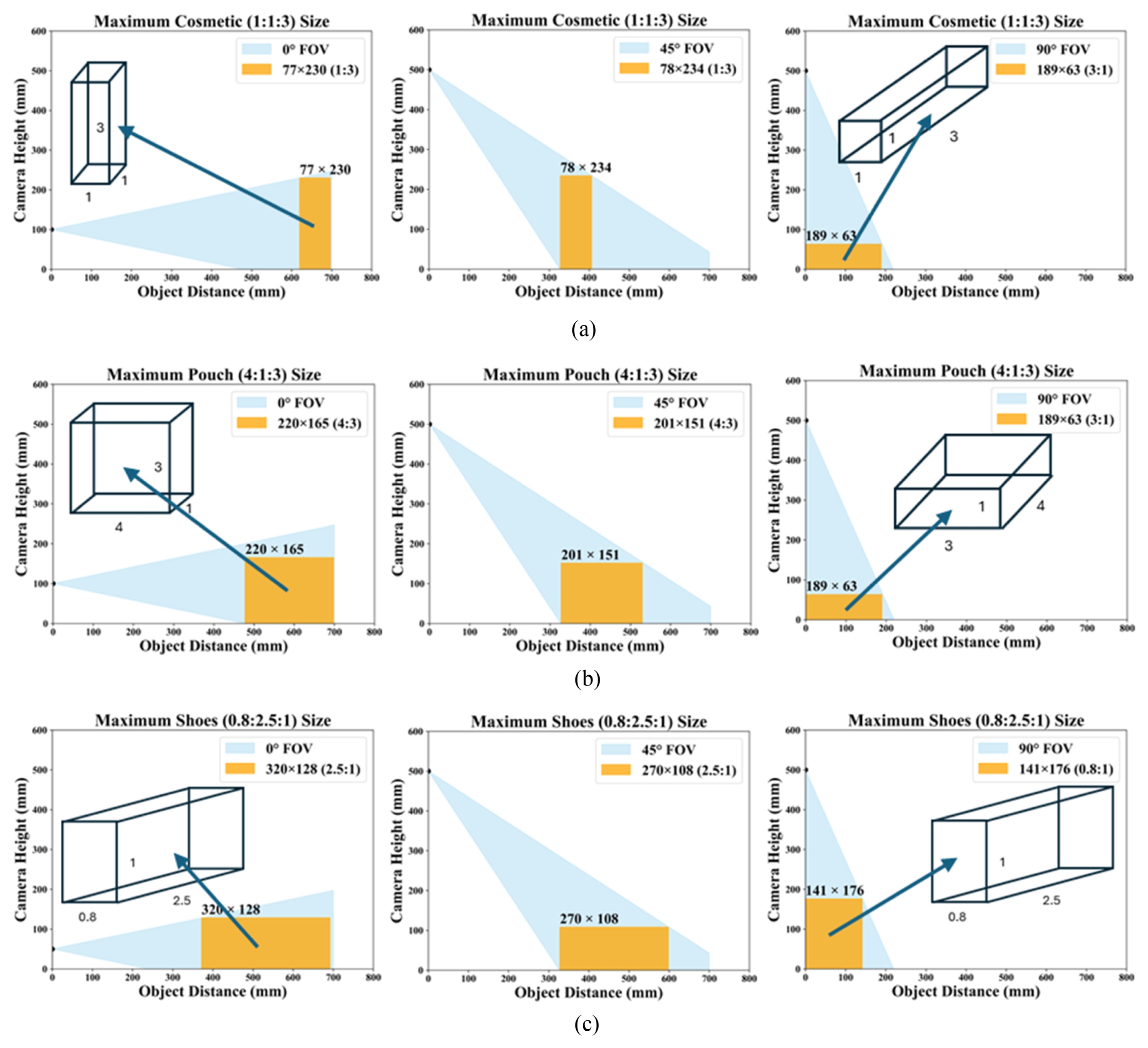
The simulation results are presented in
Figs. 2(a)-
2(c), illustrating the maximum permissible object dimensions (width, depth, and height) for tilt angles of 0, 45, and 90°, respectively. As the tilt angle increases, the effective viewable region shifts away from the object, resulting in a reduced allowable object size. Based on these results and the predefined aspect ratios, representative object dimensions were selected for each category.
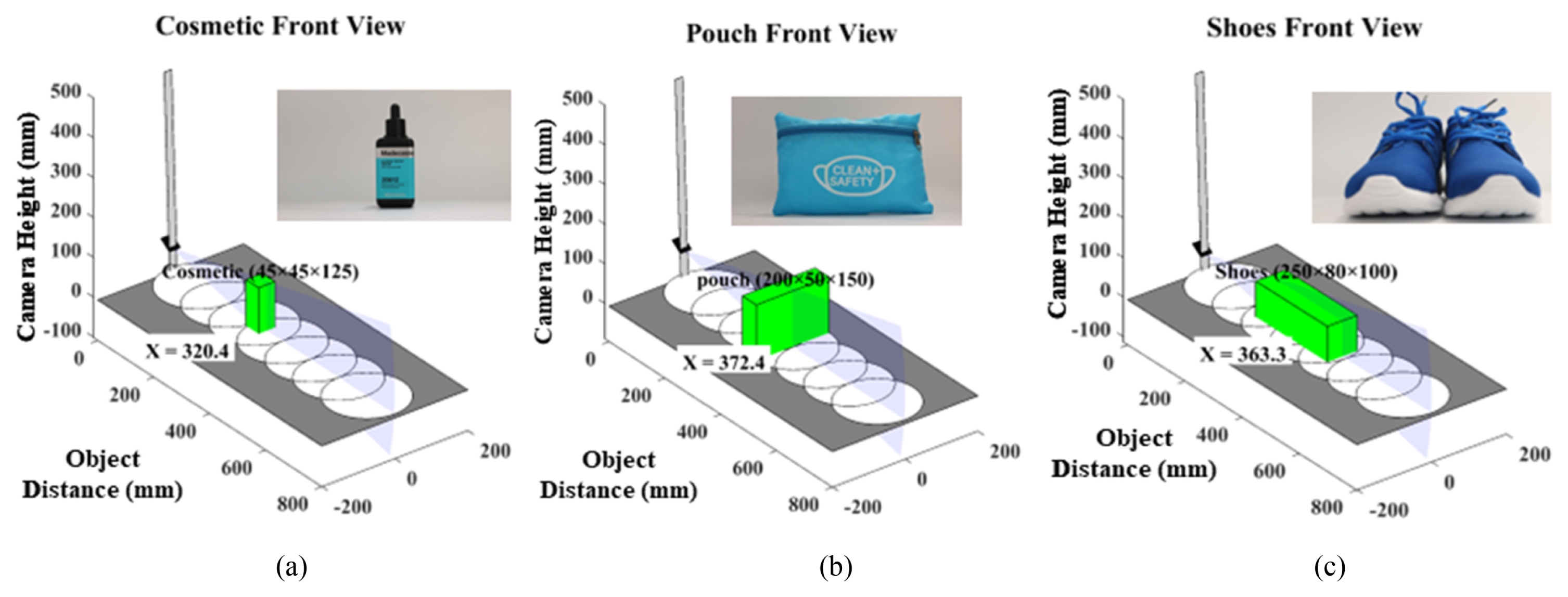
Fig. 3 shows the frontal views of the selected cosmetics, pouch, and shoes positioned within the camera FOV, along with their corresponding positions along the X-axis. All configurations were confirmed to lie within the operational limit of 700 mm, verifying that the selected objects are suitable for automated photography using the proposed robotic system.
2.3 System Integration
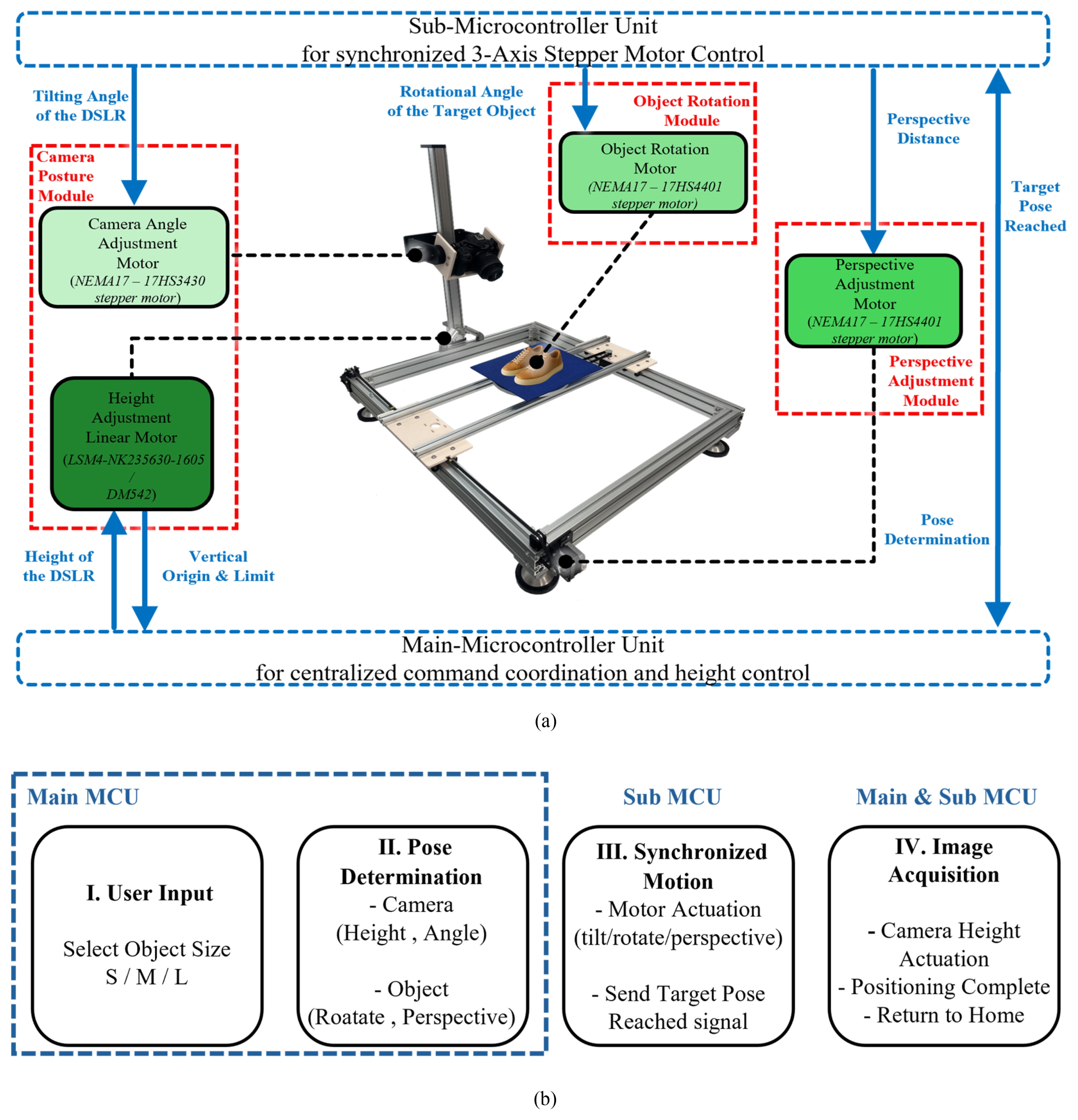
The proposed robotic system integrates hardware and software systems into a unified architecture that enables fully automated product photography. As shown in
Fig. 4(a) illustrates the overall control of architecture. Main Microcontroller Unit manages systemlevel coordination and direct control of the camera height, while delegating synchronized multi-axis operations to a Sub-MCU.
To clarify the operation,
Fig. 4(b) illustrates the detailed control logic of the system. The sequence begins with the selecting the object size category. The Main MCU then calculates the required target positions for the vertical axis and transmits the corresponding motion parameters for the tilt, rotation, and horizontal axes to the Sub-MCU via UART communication. The Sub-MCU interfaces with a 3-axis CNC shield to generate stepper motor signals that actuate the corresponding mechanical modules. Upon receiving the input, the Sub-MCU actuates the motors and sends a completion signal back to the Main MCU. Only after confirming that all axes have reached their target poses via this synchronized command-and-acknowledge sequence, the Main MCU actuates the linear ball-screw motor for height adjustment and finally establish the ready state for capture. This hierarchical architecture leads to inevitable communication delays due to UART communication but does not impede system stability. Since the target application is a static photograph, it exploits the “stop and standby” signal between the main MCU and the sub MCU to avoid motion blur or positional error during the image acquisition phase. This discrete control improves reliability and simplifies coordinating multi-axis movement, ensuring consistent and repeatable operation, which is critical for generating uniform product images at e-commerce scales.
3. Performance Evaluation
The final system, developed through the Design, Fabrication, and System Integration described above, must demonstrate a certain level of operational stability and repeatability. To evaluate this operational stability, visual indicators were introduced. These indicators were used to assess the final images obtained through the robotic system.
3.1 Evaluation Set-up
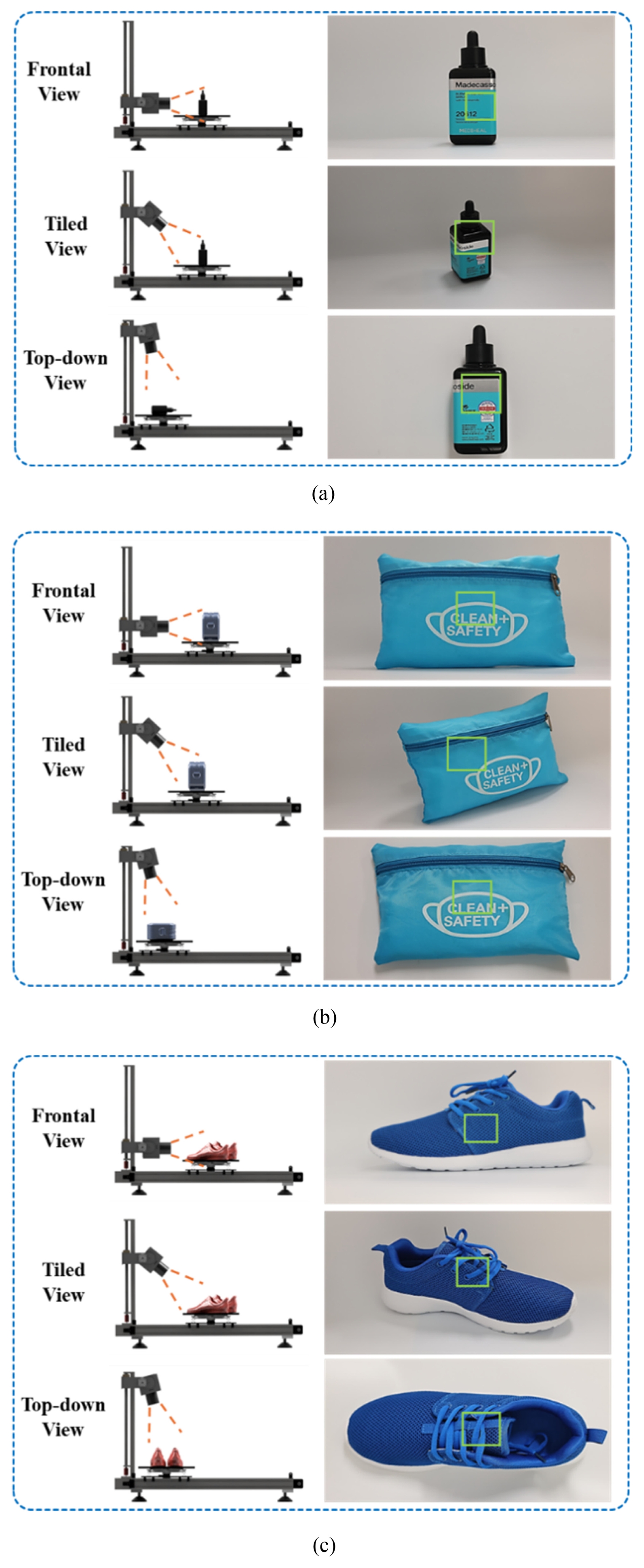
To evaluate the overall performance of the robotic system, we selected a product line with a relatively formal photographic composition among various product lines in the e-commerce market. The product line is cosmetics, pouches, and shoes, and there are various morphological and size differences between the product lines. According to the size limit of the subject assumed in the workspace evaluation above, we proceeded with the evaluation by setting cosmetics as small product lines, pouches as medium product lines, and shoes as large product lines. Various variables were controlled to conduct the evaluation, and the robotic system automatically takes photos only in three compositions: Front View, Tilted View, and Top-down View, which are representative compositions of e-commerce product photos, and performs a performance evaluation of the composition. All modules in the system are initialized for each implementation to maintain the consistency of the output results, and the evaluation results for the consistency of the image composition are presented in
Fig. 5.
Fig. 5 shows the photographing results of the robotic system for each product group (cosmetics, pouches, and shoes) in three compositions (Frontal view, Tilted view, and Top-down view). First, looking at the product photos of cosmetics (45 × 45 × 125 mm), which are small-size products, the Frontal view and the Tilted view can be used as typical main images of e-commerce products, and it can be confirmed that the image was effectively shot by the robotic system. At the same time, the top-down view is an essential image when important information such as ingredient labels attached to products should be shown to consumers. Even in this view, it can be confirmed that an image of high quality was photographed, sufficient for consumers to check the details. When the pouch (200 × 50 × 150 mm) was photographed in the same way, it was confirmed that the unstructured border and volume, which are the characteristics of the product called the pouch, were expressed in various ways in each of the three views. In the case of shoes (250 × 80 × 100 mm), the Front view and the Tilted view represent the unique appearance of the shoe to provide sufficient information to consumers, and in the case of a Top-down view, the overall size, excluding the depth of the shoe, can be effectively expressed. Through this qualitative evaluation of the three product groups, it was confirmed that the robotic system can produce suitable product images for e-commerce, and it was suggested that the characteristics of the product or essential information can be provided to consumers in various compositions. This qualitative performance evaluation shows that the robotic system we developed has a certain level of reliability and efficiency when used in a standardized product line and composition.
To rigorously evaluate the mechanical repeatability of the system, all image acquisition procedures in the evaluation set-up used the following methods. Instead of continuously shooting from a fixed position, each iteration controlled the robot to fully return to its initial home position and then move back to its target position. This procedure enables numerical indicators related to the bounding box to identify systematic errors such as fine backlash of gears, variability in belt tension, and accumulation of errors in the four step motors. Therefore, the evaluation results shown in
Figs. 5 and
6 indicate the actual precision of the hardware in a realistic operation cycle.
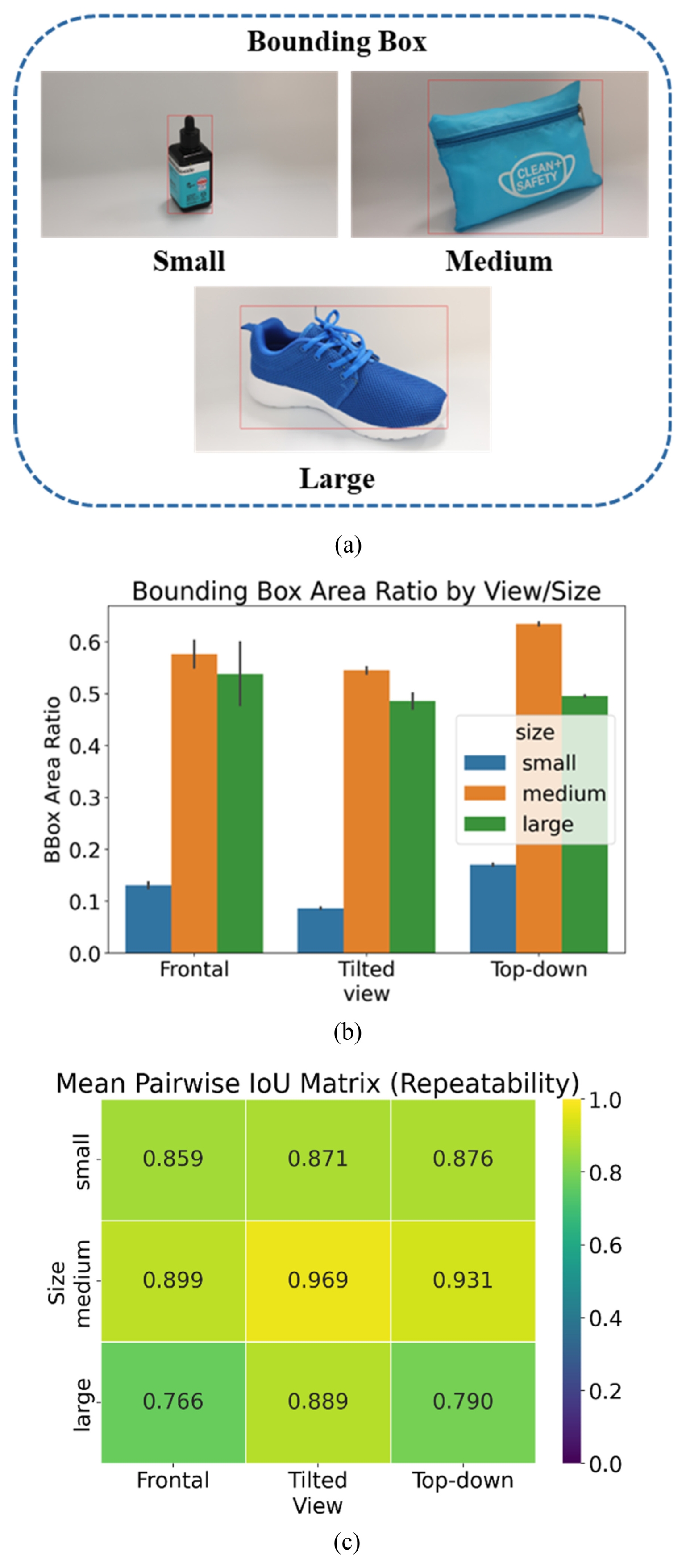
This section describes the quantitative evaluation conducted using the images taken through the above evaluation set-up. This quantitative evaluation assessed two objective evaluation indicators: perceptual stability and repeat ability. To objectively analyze these indicators, we developed an automated pipeline using Python and OpenCV. The bounding box of the target object was extracted using a hybrid algorithm combining HSV color thresholding and a YOLOv8-based detection model to ensure robustness. First, the perceptual stability index addresses the idea that when an online product photo is encountered through a display, it should be visually natural and harmonized with the UI on the page from the perspective of an actual consumer. To evaluate this quantitatively, we defined the Bounding Box Area Ratio (Rarea) to measure how largely the bounding box occupies the frame:
Where Wimage and Himage represent the width and height of the image resolution, respectively.
We analyzed these figures and confirmed that the ratio of the size of the product bounding box to the frame shows great consistency for the three compositions. In addition, this consistency was independent of the size of the product: small, medium, and large. This consistency can be interpreted as the robotic system creating a consistent perspective by varying the movement of the motor depending on the size of the product, which shows that consumers can perceive it visually and consistently regardless of the size and composition of the product. In addition, vertical alignment as an extension of the perceptual stability index also has a great influence. We defined the Normalized Vertical Offset (Evert) to evaluate the centering capability:
Where yc is the vertical center of the bounding box.
In our robotic system, horizontal alignment is not considered, so if vertical alignment is confirmed, the subject is placed in the center of the output image. As a result of evaluating this vertical alignment, all product groups and compositions were evaluated with an alignment offset smaller than 5% of the subject's height. If a real person performs photographing without such a robotic system, it is difficult to maintain a low vertical alignment error such as the above evaluation result. This is because manual photography includes unintended movements. Therefore, a low vertical alignment error can indicate a key advantage of the robotic system.
Next, in order to objectively evaluate repeat ability, the Intersection over Union (IoU) index, which is frequently used in vision technology, was used. We calculated the Mean Pairwise IoU across N = 5 repeated captures:
This index evaluates how much bounding boxes of perceived subjects overlap within the same frame. Therefore, when evaluating the repeat ability of our robotic system, repeat ability can be naturally evaluated by performing repetitive photographing at a certain composition of each product and checking how much the bounding boxes of each image overlap. Repeated photographs were taken 5 times in 3 product lines and 3 different compositions; thus 3 × 3 × 5 = 45 photographs were taken. The evaluation result is a number between 0 and 1, and the closer it is to 1, the more constant the position of the product was in the 5 repetitive photographs. As a result of the evaluation, the results ranged from a minimum value of 0.766 to a maximum of 0.969. Specifically, according to the Mean Pairwise IoU Matrix shown in
Fig. 5(c), the 'Medium' product group exhibited the highest stability, achieving a peak IoU of 0.969 in the Tilted view. The 'Small' group also showed uniform performance with values consistently ranging between 0.859 and 0.876. The 'Large' group recorded relatively lower values, including the minimum IoU of 0.766 in the Frontal view. It is more difficult to record a high number because if one image with a large error occurs in the five shots, it greatly affects the overall number. However, the fact that the results were 0.766 or higher for all products and compositions show that the location accuracy of the robotic system is excellent. This high repeat ability suggests that the synchronized motor control of the robotic system can address inconsistencies in real-world manual photography. As a result, the quantitative results of the above evaluation indicators show that the robotic system provides excellent location accuracy and repeat ability. This indicates that if the robotic system performs as well as the above evaluation indicators suggest, it can be used to shoot images of standardized products or compositions in the ecommerce market.
4. Discussion and Conclusion
In this paper, we introduced a practical solution to one of the most pressing challenges in e-commerce: the need for high-quality and visually consistent product photography. This essential business task is often constrained by the trade-off between the inconsistency of manual methods and the high costs of sophisticated industrial automation systems. Our approach aimed to bridge this gap by designing and fabricating a compact, portable robotic system that offers a practical midpoint. We adopted a fixedbase platform with four highly controlled degrees of freedomcamera height, tilt, object rotation, and lateral translation-focusing on the most critical movements required for complete product imaging. This streamlined approach allowed us to develop a system that delivers a high degree of consistency and repeat ability without the mechanical complexity, calibration demands, and cost associated with traditional multi-axis robotic arms.
In contrast to conventional robotic photography systems that typically rely on six-degree-of-freedom industrial robotic arms, the proposed system adopts a reduced four-degree-of-freedom configuration tailored to the compositional requirements of general product photography. While six-axis robotic arms provide high flexibility, many of their degrees of freedom are redundant for capturing standard product views commonly used in e-commerce. By focusing on four task-critical motions-camera height adjustment, camera tilting, object rotation, and lateral translation— the proposed system efficiently reproduces common photographic compositions while significantly reducing mechanical complexity and control overhead. This reduction in degrees of freedom contributes directly to improved operational efficiency, simplified calibration, and lower system cost.
Furthermore, the system is designed with a modular architecture, allowing individual components such as the camera module, rotation stage, or translation mechanism to be independently modified or replaced. This modularity enables users to customize the system according to their specific application requirements, such as different product sizes, camera specifications, or workspace constraints. As a result, the proposed platform not only achieves efficiency through structural simplification but also provides flexibility and scalability that are difficult to achieve with monolithic industrial robotic arms.
The success of this design process was confirmed through our quantitative evaluations. The results indicated that the system maintains excellent perspective stability, ensuring consistent product framing across different images-a key aspect for preserving brand consistency across an entire product range. In addition, the system shows high repeat ability, as evidenced by high pairwise Intersection over Union (IoU) scores, which translate to the precise alignment required for dynamic visual assets like 360-degreespins. These findings confirm the robotic system's capability to meet the essential technical demands of e-commerce photography, delivering uniform, high-quality images for any online marketplace. While the suggested system successfully addresses these core needs, it remains intentionally focused on a controlled studio environment, which leaves potential for future improvements and expanded functionality. For instance, the current system does not yet accommodate the complex, adaptive illumination needed for challenging materials, such as highly reflective metals or transparent glass. Additionally, it lacks a closed-loop feedback mechanism, which would help to mitigate minor positional drift or accidental movements during extended high-volume photo shoots. The fixed-base design, though a source of stability, limits the system’s ability to capture certain creative shots, such as photographing the interior of deep containers or achieving dramatic low-angle perspectives. Lastly, although the photographing motions themselves are fully automated, the placement and initial alignment of target objects on the platform are currently performed manually by a human operator. As a result, the present system does not yet achieve a fully automated end-toend workflow.
To address this limitation, we consider the lighting system essential, so we are planning an LED control system controlled by the existing main MCU. This allows us to avoid image loss due to shadows and reflections by adjusting the lighting profile according to the size and material characteristics of the object. We also want to address the instability of current open-loop control by applying vision recognition-based feedback control. After taking a preliminary image before feedback control, we output a feedback command by calculating the deviation between the center of the object and the center of the frame in that image through a script. The feedback command further controls the step motors to minimize the deviation between the center of the object and the center of the frame, thereby achieving accurate closed-loop control. To expand the platform's creative potential, we are also exploring structural modifications, such as a rigid arch rail, which would allow more diverse viewpoints while maintaining the system's inherent stability. Also, by integrating a simple automated loading or alignment mechanism, or by incorporating vision-based object detection and pose estimation algorithms, the object placement and orientation process could also be automated. Such extensions would enable the system to evolve from the current semi-automated pipeline into a fully automated photography platform with minimal human intervention, covering the entire process from object placement to image acquisition. Through these developments, we aim to refine the system and strengthen its position as a scalable, cost-effective alternative that can help businesses of all sizes automate and streamline their product photography processes.
FOOTNOTES
-
ACKNOWLEDGEMENT
This work was supported by the National Research Foundation of Korea (NRF) grant funded by the Korea government (MSIT) (No. RS-2024-00342395)
Fig. 1Portable camera robot for automated product photography: (a) Overall system design, (b) The design of modular components: (b-i) Camera posture (height/tilt), (b-ii) Object rotation, (b-iii) Perspective adjustment, and (c) Fabricated prototypes of each module: (c-i) Camera posture (height/tilt), (c-ii) Object rotation, (c-iii) Perspective adjustment
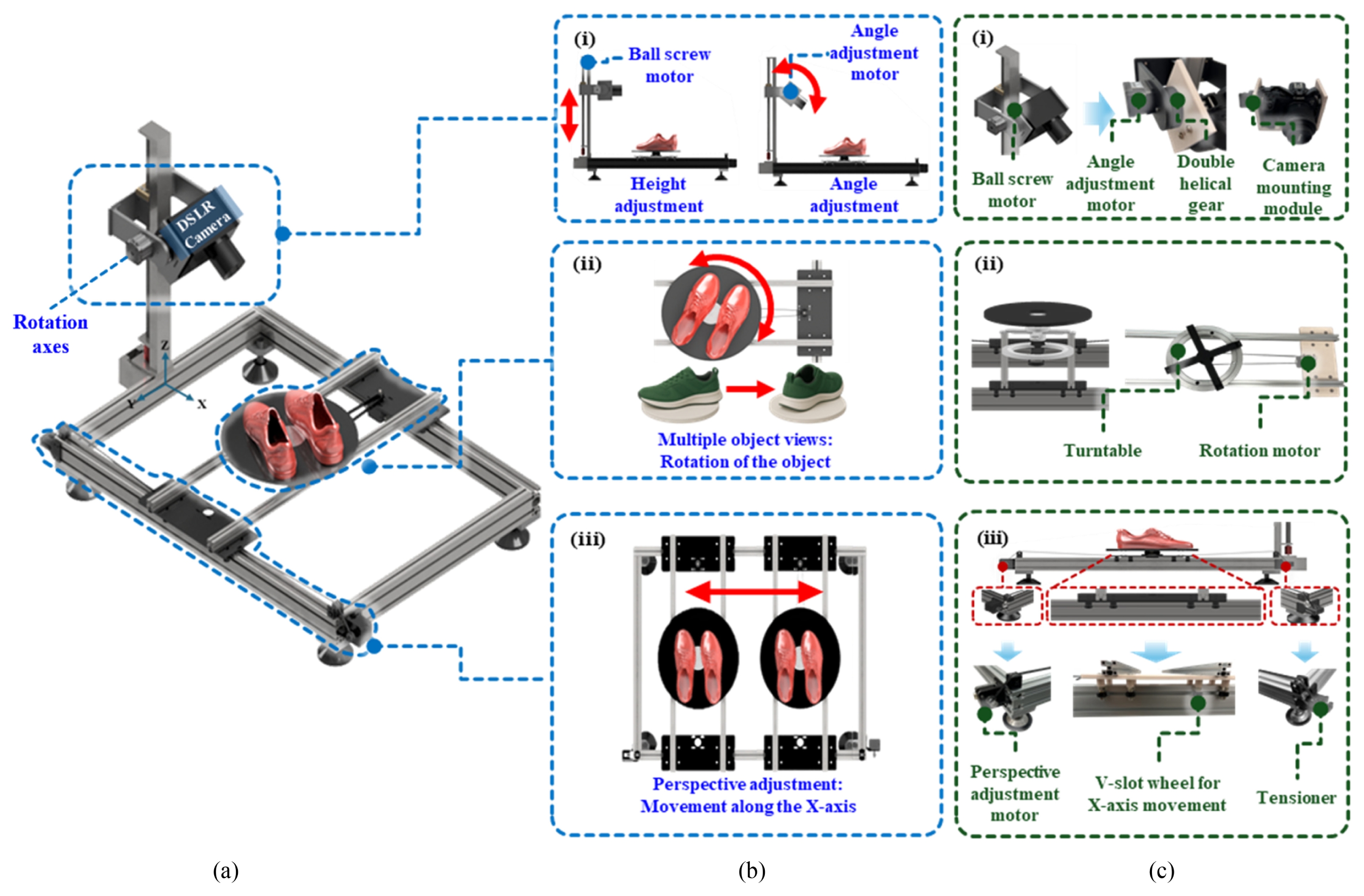
Fig. 2Simulation results showing the maximum object size that can be captured at each tilt angle (0°, 45°, and 90°) as the camera moves along the Z-axis: (a) Simulation of a cosmetic product (Width : Length : Height = 1 : 1 : 3), with frontal imaging at 0° and 45°, and top-down imaging at 90° after laying the object flat (b) Simulation of a pouch (Width : Length : Height = 4 : 1 : 3), with frontal imaging at 0° and 45°, and top-down imaging at 90° after laying the pouch flat, (c) Simulation of a shoes (Width : Length : Height = 0.8 : 2.5 : 1), with frontal imaging at 0° and 45°, and imaging at 90° after rotating the shoes by 90° relative to the frontal orientation
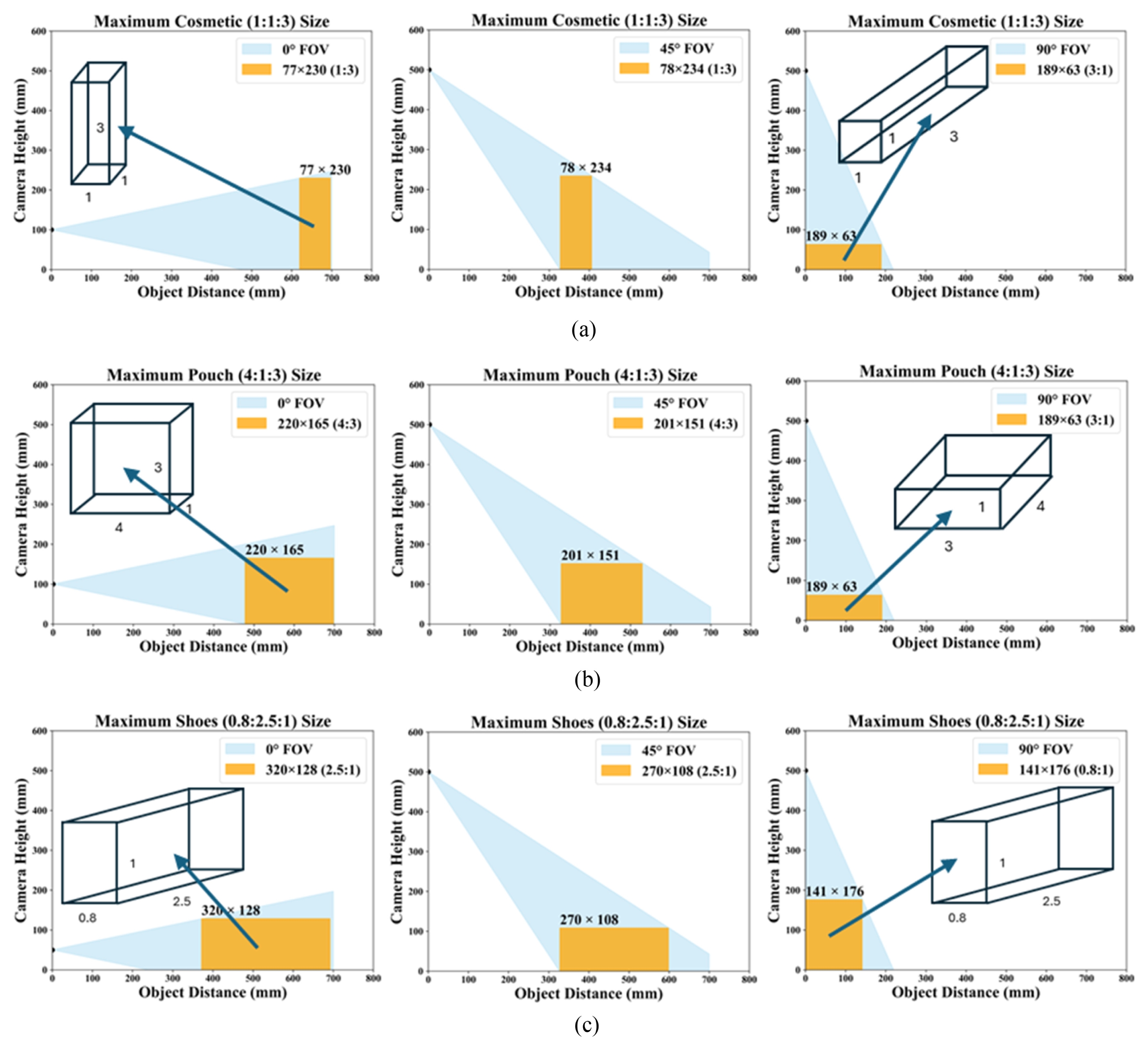
Fig. 3Workspace configuration of the camera robot in X-direction: (a) Minimum object to camera X-axis distances within the field of view for cosmetic (45 × 45 × 125 mm), (b) Minimum object to camera X-axis distances within the field of view for pouch (200 × 50 × 150 mm), (c) Minimum object to camera X-axis distances within the Field of view for shoes (250 × 80 × 100 mm)
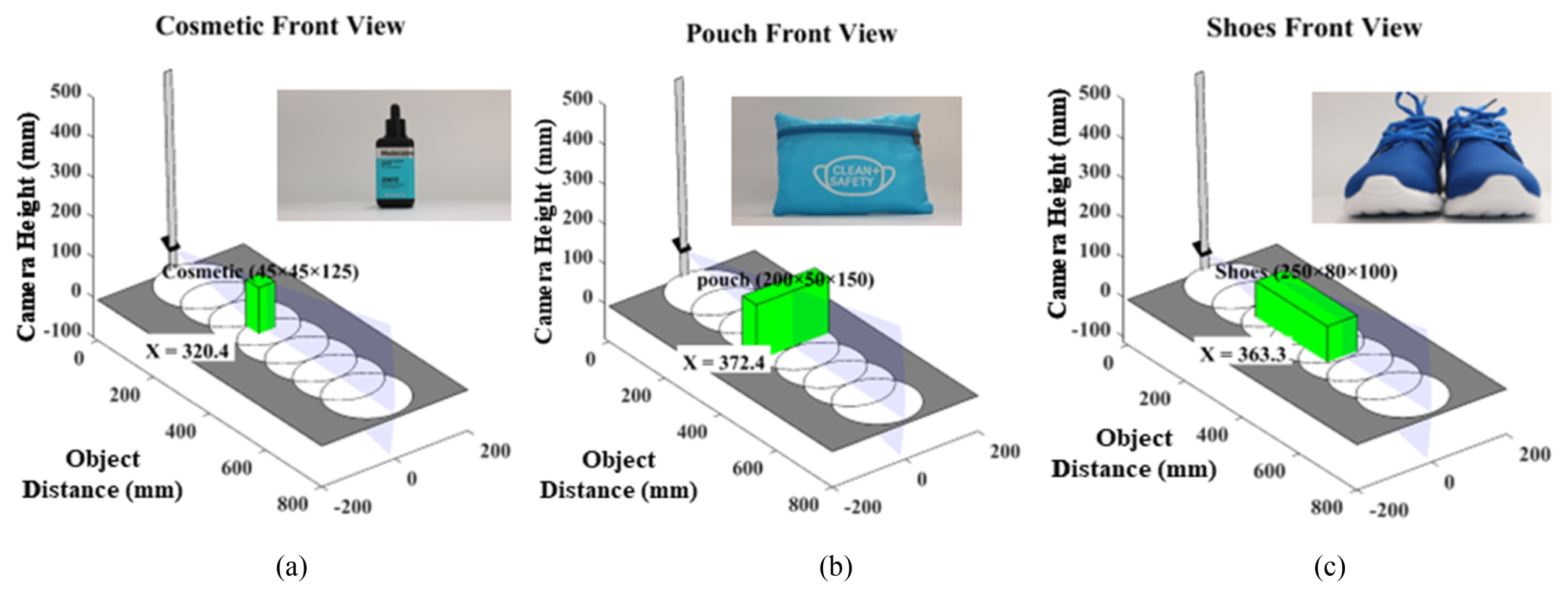
Fig. 4(a) Control architecture of the automated photography robot. Initiated by user-inputted object size, the main microcontroller manages height and directs the sub-microcontroller to perform synchronized 3-axis movements for angle, rotation, and perspective adjustments. (b) Control logic flowchart of the proposed system. It illustrates the sequential operation from user input and pose determination to synchronized motion execution, ensuring a mechanically stable state ready for image acquisition
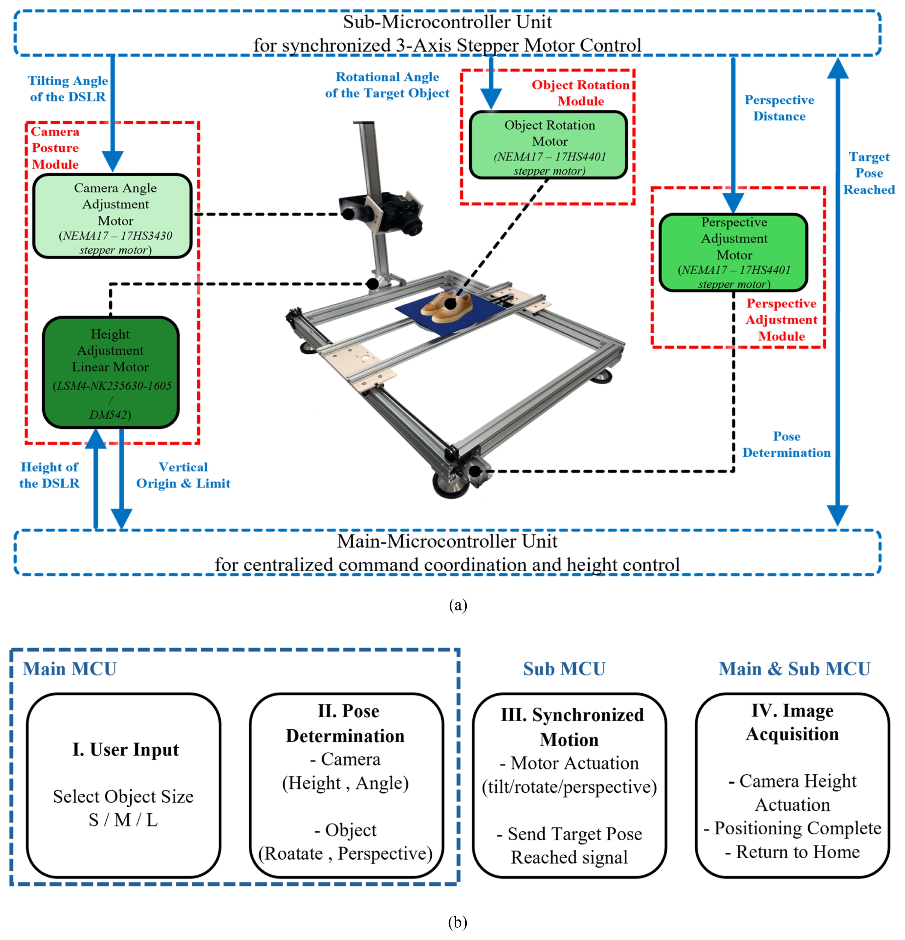
Fig. 5Performance evaluation of Portable Camera Robot for Actual Photographing: (a) Captured views of a cosmetic product (45 × 45 × 125 mm) from frontal, 45° tilted, and 90° top-down angles, (B) Captured views of a pouch (200 × 50 × 150 mm) from frontal, 45° tilted, and 90° top-down angles, (C) Captured views of shoes (250 × 80× 100mm) from frontal, 45° tilted, and 90° top-down angles
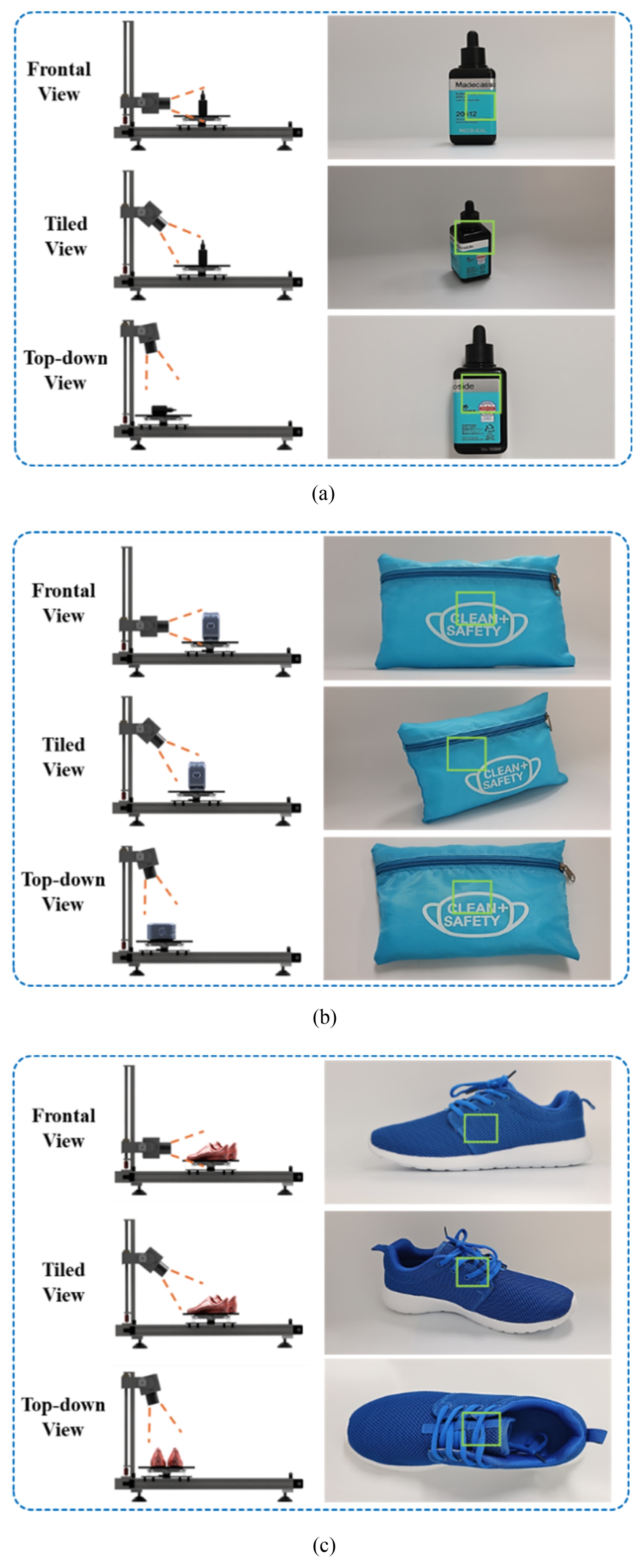
Fig. 6Evaluation of object localization consistency across different object sizes and camera views. The figure illustrates: (a) Bounding box visualization as qualitative examples of the detected regions of interest (ROI), (b) perspective consistency measured by bounding box area ratio, and (c) repeatability quantified by the pairwise IoU matrix across repeated captures (N = 5). Results indicate stable localization, with area ratios showing low variance across views and IoU values consistently above 0.75, confirming robustness of the setup
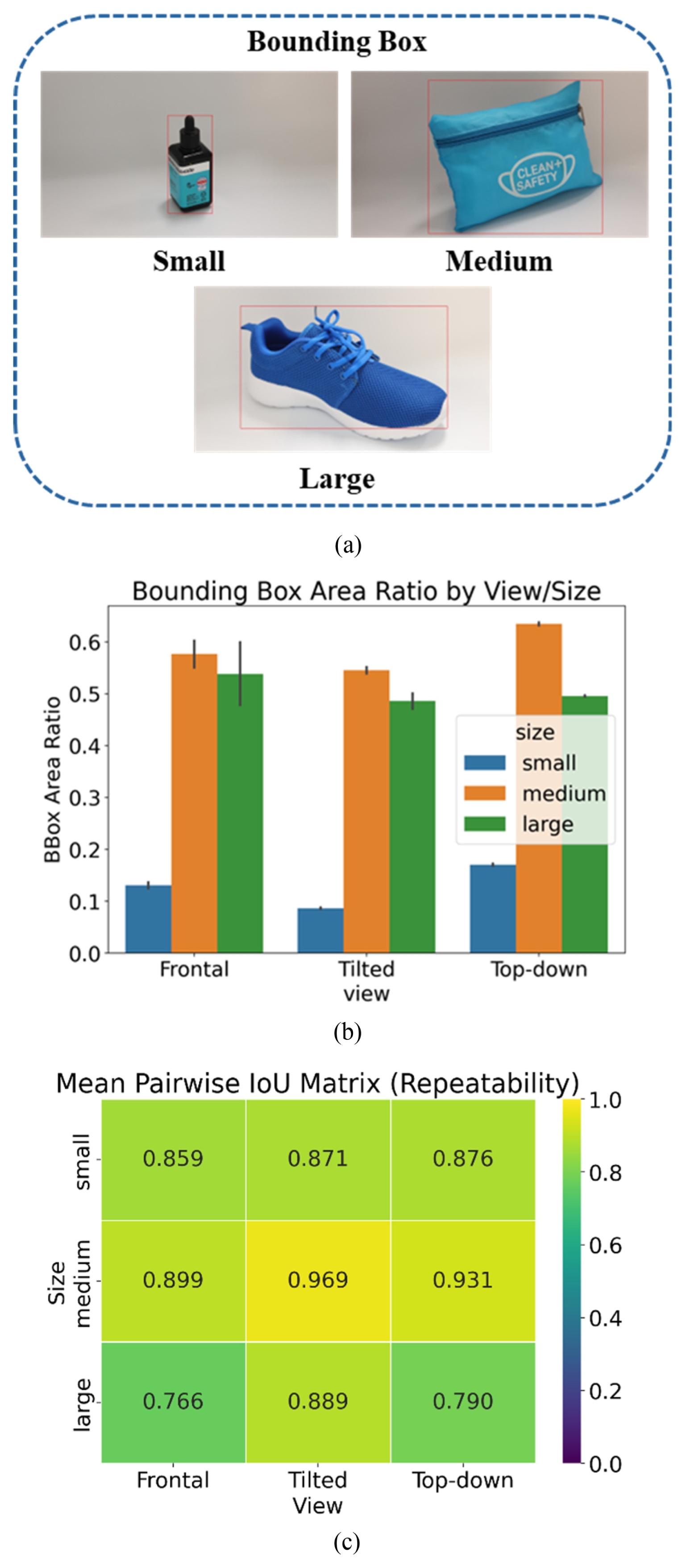
Table 1Size of the representative object
Table 1
|
Object |
Size [mm] |
Dimensional categorization |
|
Cosmetics |
45 × 45 × 125 |
Small |
|
Pouch |
200 × 50 × 150 |
Medium |
|
Shoes |
250 × 80 × 100 |
Large |
REFERENCES
- 1. Wang, M., Li, X., Liu, Y., Chau, P., Chen, Y., (2024), A contrast-composition-distraction framework to understand product photo background’s impact on consumer interest in e-commerce, Decision Support Systems, 178, 114124.
- 2. Meyers-Levy, J., Peracchio, L. A., (1992), Getting an angle in advertising: The effect of camera angle on product evaluations, Journal of Marketing Research, 29(4), 454-461.
- 3. Maros, A., Belém, F., Silva, R., Canuto, S., Almeida, J. M., Gonçalves, M. A., (2019), Image aesthetics and its effects on product clicks in e-commerce search, Proceedings of the SIGIR 2019 eCom workshop.
- 4. Maniatis, C., Saval-Calvo, M., Tylecek, R., Fisher, R. B., (2017), Best viewpoint tracking for camera mounted on robotic arm with dynamic obstacles, Proceedings of the International Conference on 3D Vision. 107-115.
- 5. Yu, C., Cai, Z., Pham, H., Pham, Q.-C., (2019), Siamese convolutional neural network for sub-millimeter-accurate camera pose estimation and visual servoing, Proceedings of the IEEE/RSJ International Conference on Intelligent Robots and Systems (IROS). 935-941.
- 6. Byers, Z., Dixon, M., Smart, W. D., Grimm, C. M., (2004), Say cheese! Experiences with a robot photographer, AI Magazine, 25(3), 3-96.
- 7. Byers, Z., Dixon, M., Goodier, K., Grimm, C. M., Smart, W. D., (2003), An autonomous robot photographer, Proceedings of the IEEE/RSJ International Conference on Intelligent Robots and Systems. 2636-2641.
- 8. Tan S., Smith N. C., Padilla K., Ashley E.. 2018;Autonomous ground photographer, Mechanical Engineering Design Project Class. Washington University in St. Louis. https://openscholarship.wustl.edu/mems411/90/.
- 9. Lan, K., Sekiyama, K., (2019), Autonomous robot photographer with KL divergence optimization of image composition and human facial direction, Robotics and Autonomous Systems, 111, 132-144.
- 10. Fteiha, B., Altai, R., Yaghi, M., Zia, H., (2024), Revolutionizing video production: An AI-powered cameraman robot for quality content, Engineering Proceedings. 60(1):19.
- 11. Zabarauskas, M., Cameron, S., (2014), Luke: An autonomous robot photographer, Proceedings of the IEEE International Conference on Robotics and Automation. 1809-1815.
- 12. Kamarianakis, Z., Perdikakis, S., Daliakopoulos, I. N., Papadimitriou, D. M., Panagiotakis, S., (2024), Design and implementation of a low-cost, linear robotic camera system, targeting greenhouse plant growth monitoring, Future Internet, 16(5), 145.
- 13. Ashwin, C., (2014), Camera platform control for video scanning, International Journal of Engineering Research & Technology, 3(5), 77-81.
- 14. Konecny, J., Beremlijski, P., Bailova, M., Machacek, Z., Koziorek, J., Prauzek, M., (2024), Industrial camera model positioned on an effector for automated tool center point calibration, Scientific Reports, 14(1), 323.
- 15. Kusumandyoko, T. C., Marsudi, M., Islam, M. A., Abidin, M. R., (2025), Optimizing product photo for effective e-commerce, Proceedings of the International Joint Conference on Arts and Humanities, Atlantis Press.
- 16. Kang S., Lee J.. 2024;Electronic device and method for taking picture thereof. KR. 102714033B1.
- 17. Floss, S., Maesgen, M. M., Kamps, M., Wurlitzer, L., (2019), Photography system. US. 10225447B2.
- 18. Verma, A., Bubna, N., (2018), Product photography machine. WO. 2018087781A1.
- 19. Lai, P.-C., (2007), Computer controlled system for synchronizing photography implementation between a 3-D turntable and an image capture device with automatic image format conversion. US. 20070172216A1.
- 20. Chen, X.-P., Zhou, C.-F., (2010), Computer-controlled physical three-dimensional automatic imaging device with light and horizontal rotating table. CN. 101916036A.
Biography
- Jae Hyun Yoon
B.Sc. graduate in the School of Mechanical Engineering, Konkuk University. His research interest is automation robotics.
- Jun Seo Bae
B.Sc. candidate in the School of Mechanical and Aerospace Engineering, Konkuk University. His research interest is automation robotics.
- Jin-Ho Choi
M.S. Candidate, Konkuk University B.Sc. Department of Electronic Engineering, Korea National University of Transportation His research interest includes robotics haptic systems and electroactive actuators
- Sunghoon Kang
CEO, STUDIO LAB Co., Ltd. M.S. in Information Management, Korea Advanced Institute of Science and Technology (KAIST) His research interests include robotics, artificial intelligence and autonomous commerce content generation systems.
- Jaeyoung Lee
COO, STUDIO LAB Co., Ltd. M.S. candidate in the Future studies, Korea Advanced Institute of Science and Technology (KAIST) His research interests include artificial intelligence, robotics and autonomous content generation systems
- Tae-Heon Yang
Associate Professor, Department of Mechanical Engineering, Konkuk University Ph.D., Korea Advanced Institute of Science and Technology (KAIST) His research interest includes robotics, haptic systems, electroactive actuators and human-machine interfaces.