ABSTRACT
Solid Oxide Fuel Cells (SOFCs) are energy conversion devices known for their significantly higher power density compared to other fuel cell types. However, their high operating temperatures pose challenges related to thermal stability. To address this, research is focusing on Low-Temperature SOFCs (LT-SOFCs), which function at lower temperatures and exhibit enhanced electrochemical performance. While various electrode materials are utilized in SOFCs, platinum (Pt) stands out for its excellent electronic conductivity and catalytic activity. Unfortunately, at the operating temperatures of SOFCs, Pt tends to agglomerate, leading to a rapid reduction in the triple phase boundary (TPB) and a subsequent decline in electrochemical reactions. In this study, LT-SOFCs were fabricated with a Praseodymium Oxide (PrOx) capping layer applied to a porous Pt cathode using sputtering, with various thicknesses achieved by adjusting the deposition time. The electrochemical performance of the LT-SOFCs was measured at 500oC. Additionally, the degradation behavior of the LT-SOFCs was assessed by applying a constant voltage of 0.5 V for 48 hours. Scanning Electron Microscopy (SEM) analysis was also conducted on the PrOx capping layer thin films under the same operating conditions.
-
KEYWORDS: Solid oxide fuel cells, Praseodymium oxide, Capping layer, Sputtering process, Electrochemical impedance spectroscopy
-
KEYWORDS: 고체산화물 연료전지, 프라세오디뮴 산화물, 캡핑층, 스퍼터링 공정, 전기화학 임피던스 분광법
1. Introduction
Fuel cells are devices that convert chemical energy into electrical energy and are receiving significant attention today, where environmental issues are emphasized. Among them, Solid Oxide Fuel Cells (SOFCs) are known as devices with excellent thermal efficiency [
1-
4]. However, due to the high-temperature operating environment, SOFCs still have many issues to be addressed in terms of material selection and long-term stability [
5-
7]. In particular, if the operating temperature of conventional SOFCs is simply lowered, the electrochemical performance drops significantly.
Therefore, research on LT-SOFCs (Low-temperature SOFCs), which lower the operating temperature to below 600
oC and enhance electrochemical performance, is being conducted. In various previous studies, perovskite materials which are mixed-ionic electron conductors, have already been applied to the electrodes of LT-SOFCs and have shown excellent performance even at the relatively low operating temperature of below 600
oC [
8-
12]. Meanwhile, Pt is the promising cathode materials in LTSOFCs. On the Pt surface, oxygen molecules (O
2) can dissociate into atomic oxygen (O) with a relatively low energy barrier [
13]. In addition, due to its high electrical conductivity, Pt enables efficient electron transfer required for the oxygen reduction reaction (ORR) [
7,
14-
15]. According to previous studies, Pt exhibits excellent ORR activity even at low temperatures below 500
oC [
13,
16]. However, Pt easily undergoes agglomeration at the operating temperature of SOFCs. Agglomeration is a phenomenon that occurs when thermal energy is applied to a Pt film or nanoparticles, causing Pt atoms or clusters to migrate toward regions of lower surface energy [
17,
18]. This reduces the triple phase boundary (TPB), thereby decreasing the effective area available for electrochemical reactions and ultimately leading to a drop in cell performance. Furthermore, as Pt particles undergo agglomeration, the originally continuous conductive pathways break down into a discontinuous network of isolated particles [
19]. This disrupts electron transport within the electrode, and further degrades the overall operational efficiency of the cell.
Accordingly, the cathode capping layer is a thinly coated layer on the top of the cathode that helps improve electrochemical performance by enhancing catalytic activity and reducing interfacial resistance. According to previous research by Ji, alumina capping agents fabricated through the atomic layer deposition (ALD) process showed lower ohmic resistance than Pt cathodes [
20]. In addition, Liu applied a ZrO₂ capping layer to nanoporous Pt cathodes and analyzed the thermal stability and polarization resistance changes [
21]. Furthermore, according to previous research by Hong, the electrochemical performance was improved by fabricating a capping layer of GDC through a sputtering process [
22].
Praseodymium oxide (PrO
x) is an oxide containing the rareearth element Pr, characterized by the coexistence of various oxidation states such as Pr
3+ and Pr
4+ [
23-
25]. In particular, due to the mixed valence state of PrO
x, it exhibits MIEC properties, allowing both electronic conduction and ionic conduction through oxygen vacancies [
26]. It also has excellent oxygen storage capacity (OSC), enabling free storage and release of oxygen ions. Due to these reasons, PrO
x exhibits outstanding catalytic activity [
27,
28]. Moreover, it has been previously reported that the addition of Pr
6O
11 to LSM facilitates oxygen ion transport by creating new ion conduction channels and expanding active reaction sites, which in turn leads to a substantial reduction in polarization loss [
29]. However, there has been no research on capping layers fabrication of PrO
x using the PVD process. In this study, a PrO
x capping layer will be fabricated using the sputtering process, and the electrochemical performance of LT-SOFCs will be evaluated accordingly.
2. Experiments
As shown in
Fig. 1, reaction area of 1 mm
2 LT-SOFCs was fabricated. A 180 μm-thick Sc₂O₃-stabilized zirconia (ScSZ) pellet was used as the electrolyte support. ScSZ possesses excellent mechanical strength and shows the highest oxygen ion conductivity [
2,
7,
30]. Additionally, all electrodes and capping layer were fabricated by sputtering (KVS-2000L, Korea Vacuum Tech, Gimpo-si, Republic of Korea). Sputtering offers the advantage of enabling deposition technique within cost and efficiency [
31]. The cathode was deposited using a Pt target (VTM, Incheon, Republic of Korea). Porous Pt was deposited for 5 minutes at a DC power of 100 W, with an Ar gas flow rate of 30 sccm supplied under a pressure of 50 mTorr. The anode was deposited using a Ni target (VTM, Incheon, Republic of Korea). Ni has high electrical conductivity and excellent catalytic properties for the Hydrogen Oxidation Reaction (HOR). Ni was deposited by applying a DC power of 100 W, with an Ar gas flow rate of 30 sccm, under a working pressure of 30 mTorr. The parameters for electrode fabrication are shown in
Table 1, under the same conditions as the previous study [
7].
The PrO
x layer was deposited using a Pr
6O
11 target (VTM, Incheon, Republic of Korea) via a reactive sputtering process. Although reactive sputtering has the disadvantage of a low deposition rate, it offers the advantage of achieving excellent uniformity in oxide thin films. The deposition process for PrO
x was based on previous study, and was carried out under a process pressure of 5 mTorr by supplying Ar gas at 24 sccm and O
2 gas at 6 sccm into the chamber, with an RF power of 40 W applied. In our previous work, the PrO
x thin film deposited for 1 hour was identified to have a thickness of approximately 30 nm through SEM analysis, corresponding to a deposition rate of 0.5 nm/min [
7]. The films were deposited for various durations. The PrO
x layers were subdivided based on PrO
x deposition time, as shown in
Table 2.
Additionally, thin films identical to the LT-SOFCs cathode were deposited on a Si wafer, and annealing was performed at 500oC for 48 hours. Subsequently, Scanning Electron Microscopy (SEM) was conducted to examine the surface behavior of both the as-deposited and annealed cases.
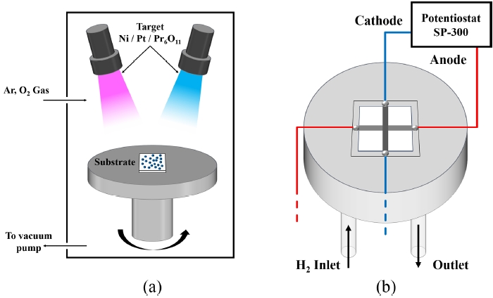
To investigate the electrochemical performance of LT-SOFCs, custom-made SOFC test station setup was used, as shown in
Fig. 3. Each electrode was connected by Ag wire and Ag paste (Silver Conductive Ink Liquid S-020, Alfa Aesar, Haverhill, MA, USA). After connecting the Ag paste, the sample was heat-treated at 200
oC for 1 hour in air to ensure electrical conductivity between the cell and the wire. To prevent gas leakage, ceramic sealant (Ceramabond 571, Aremco, Valley Cottage, NY, USA) was used. Cell tests were conducted at 500
oC. Hydrogen gas (H
2) was supplied at a flow rate of 50 sccm at 1.2 bar by mass flow controller. On the other hand, the cathode was exposed to atmosphere. Electrochemical properties were measured using potentiostat (SP-300, Biologic, Seyssinet-Pariset, France). After measurements of the cell performance, electrochemical impedance spectroscopy (EIS) was analyzed by applying an alternating current perturbation of 10 mV at 0.7 V over a frequency range of 1 Hz to 1 MHz. In addition, to evaluate the thermal stability of the LT-SOFCs, the current density was measured under a constant voltage of 0.5 V for 48 hours.
3. Results & Discussion
3.1 Analysis of Pt Cathode with PrOx Capping Layer
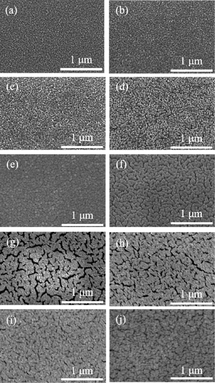
Fig. 3 shows differentiated PrO
x capping layers according to deposition time, as well as the results for the as-deposited samples and those annealed for 48 hours. During the SEM analysis of the PrO
x capping layer deposited on the 150 nm-thick Pt cathode, no additional Pt coating was applied in order to avoid distortion of the uniformity of layers.
Fig. 3(a) shows the pure Pt case without the PrO
x capping layer.
Figs. 3(b) is the case where PrO
x layer was deposited for 5 minutes,
3(c) for 10 minutes,
3(d) for 20 minutes,
3(e) is the case where PrO
x was deposited for 60 minutes. In addition,
Figs. 3(f)-
3(j) correspond to the cases in
3(a)-
3(e) after annealing at 500
oC for 48 hours.
In the case of pure Pt, where no PrO
x was deposited, it is visually evident that the particle size increases after annealing at 500
oC for 48 hours compared to the as-deposited state. This observation is consistent with previous studies, which have reported similar tendencies for particle growth under comparable temperature conditions [
17-
21]. As the particle size increases after annealing, the electrochemically active surface area (ECSA) of the catalyst decreases, and the TPB density is reduced [
32].
Consequently, this leads to a deterioration in electrochemical performance.
Figs. 3(b) and
3(f) correspond to the as-deposited and the annealed (500
oC, 48 hours) states of the Pr05 case, respectively. Similar to the pure Pt case, agglomeration of Pr05 was also observed after annealing. However, the grain size tended to be smaller compared to Pure Pt case. Unlikely, Pr05 case has increasement in void spaces. This phenomenon can be attributed to the excessively thin PrO
x capping layer, which only partially and discontinuously covers the Pt surface [
33,
34]. As a result, the diffusion of Pt atoms is only partially suppressed, leading to the growth of isolated Pt particles. Consequently, the continuity between particles is weakened, and voids are formed between the grains. According to the previous study by Galinski, oxide interfaces influence the surface energy and diffusion behavior of metal thin films. In particular, it has been reported that a lower adhesion energy at the interface between oxides and metals results in the formation of more void spaces [
32].
Furthermore, previous study demonstrated that even trace amounts of oxide present on the surface or at the interface of metal thin films inhibit the free coalescence of particles, leading to the growth of particles in an island-like morphology [
35]. In contrast, as shown in
Figs. 3(h)-
3(j) which correspond to the Pr10, Pr20, and Pr60 cases after annealing at 500
oC, a noticeable reduction in void formation can be observed compared to the Pr05 case. This suggests that, as the PrO
x capping layer becomes relatively thicker than Pr05, it is able to cover the Pt surface in a more continuous and uniform. The increased thickness of the PrO
x layer likely acts as a more effective barrier, suppressing the surface diffusion and movement of Pt particles. Therefore, the tendency for Pt particles to agglomerate and form isolated islands is significantly reduced, and the overall film morphology becomes denser and more cohesive, with fewer voids present between the grains [
3]. This observation indicates that the continuity and uniformity of the oxide capping layer play a critical role in controlling the microstructural evolution of the Pt thin film during high-temperature annealing.
To confirm the presence of Pr particles, the Pr60 sample was annealed at 500
oC for 48 hours, followed by Energy Dispersive X-ray Spectroscopy (EDS) analysis. The EDS results revealed that the atomic ratio of Pt to Pr was 22.56 at% to 2.88 at%. As shown in
Fig. 4, elemental mapping was performed based on the EDS data. These results indicate that PrO
x, which contains a high concentration of oxygen vacancies, remains on the surface even after prolonged annealing at 500
oC, without being desorbed [
23,
24].
Figs. 5(a) shows the j-V-P curves of LT-SOFCs measured at 500
oC for each case, and 5(b) shows the comparison of maximum power density of LT-SOFCs. In all cases, the open-circuit voltage (OCV) was above 1.0 V and showed stable state. For Pure Pt without PrOₓ capping layer, the maximum power density was 24.4 mW/cm
2, for Pr05 it was 28.3 mW/cm
2, for Pr10 it was 31.7 mW/cm
2, and for Pr20 it was 38.0 mW/cm
2. This shows that PrOₓ capping layer promotes the electrochemical reaction up to 55%. On the other hand, Pr60, which had the thickest PrOₓ capping layer, showed a performance of 35.3 mW/cm
2, which is about 7.65% lower than Pr20.
Fig. 6(a) shows the EIS results of Pr20 case, which has highest maximum power density, at OCV, 0.7 V, and 0.5 V. And
Fig. 6(b) shows the EIS results of LT-SOFCs measured at 0.7 V. The equivalent circuit at the top of the EIS is composed of resistors (R) and constant phase elements (Q). The EIS is plotted as a Nyquist plot, and the starting point of the small semicircle on the real axis is the ohmic resistance [
1,
7,
8]. Additionally, the arcs of the small and large semicircles correspond to the faradaic resistance. As shown in
Table 3, the ohmic resistance of Pure Pt is 4.90 Ω·cm
2, which is the largest value of all cases. The ohmic resistance of Pr05 is 4.60 Ω·cm
2, showing a 6.12% reduction compared to Pure Pt. Also, Pr10 and Pr20 have values of 4.47 and 3.13 Ω·cm
2, respectively, confirming a progressive decrease. This is because PrO
x has the property of MIEC, when applied as a capping layer, it can transport both oxygen ions and electrons, enabling charge transfer within the PrO
x layer. This expands the charge transfer pathway beyond the Pt cathode-electrolyte interface to include the PrO
x layer and the PrO
x-Pt boundary, therefore reduces electrical resistance [
23,
36]. On the other hand, in the case of Pr60, the ohmic resistance increases again to 4.08 Ω·cm
2, which is attributed to the fact that although the charge transfer pathways are expanded, the length of the ion transport path becomes much longer than in the other cases [
7].
Regarding the faradaic resistance, Pure Pt is 6.37, Pr05 is 4.52, Pr10 is 4.16, Pr20 is 3.87, and Pr60 is 3.42 Ω·cm
2. This indicates that as the PrO
x capping layer increases, the faradaic resistance decreases. This is because the uniform distribution of PrO
x nanoparticles on the cathode surface increases active reaction sites and improves the efficiency of oxygen adsorption and dissociation, resulting in enhancement of the TPBs [
37]. Furthermore, PrO
x, which is rich in the Pr
3+ and Pr
4+ redox pair, improves the surface exchange coefficient and accelerates the ORR rate [
20-
23].
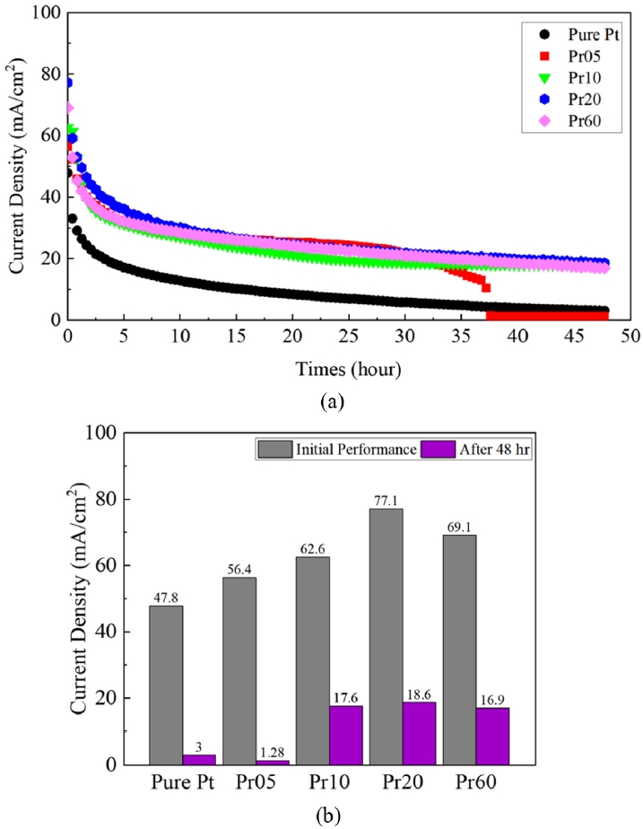
Fig. 7 shows the results of a short-term stability test conducted for 48 hours at a temperature of 500
oC under a constant voltage of 0.5 V. The initial current density of Pure Pt was 47.8, Pr05 was 56.4, Pr10 was 62.6, Pr20 was 77.1, and Pr60 was 69.1 mA/cm
2. However, after 48 hours, pure Pt decreased to 3 mA/cm
2. This is due to the fact that at 500
oC, Pt agglomeration occurs, leading to a decrease in TPB and consequently a reduction in reaction sites [
16]. Interestingly, Pr05 showed a similar trend to the other PrO
x-capped samples, but it sharply decreased to 1 mA/cm
2 around 37 hours. SEM analysis notably showed that Pr05 exhibited the highest density of voids among the samples. This suggests that the PrO
x layer in Pr05 failed to form a continuous protective film, resulting in insufficient connectivity between Pt particles and an inherently unstable nanostructure. Therefore, the increased interparticle distance, combined with the non-uniformity of the PrO
x thin film, leads to the disruption of continuous electronic and ionic transport pathways [
38]. This interpretation is reported by previous studies on nanoparticulate thin films, which have shown that increased voids interrupt conductive pathways and significantly degrade electrical properties [
38,
39]. Pure Pt case undergoes gradual performance degradation due to the diffusion and agglomeration of Pt particles over time, resulting in TPB reduction. In contrast, Pr05 not only experiences TPB reduction similar to Pure Pt but also suffers from agglomeration process irregularities caused by an excessively thin PrO
x capping layer. This structural vulnerability leads to an increased void density, destabilizing the connectivity among Pt particles and ultimately causing the blocking of electronic and ionic transport pathways.
On the other hand, for Pr10, Pr20, and Pr60, a steady degradation was observed without a drop in current density. Unlike Pr05, these still allow some flow of oxygen ions and electrons, and partially maintain MIEC. In contrast to the Pr05 case, resulting in a noticeable reduction in voids and the formation of a more continuous and uniform protective coating. This enhanced continuity and increased thickness of the capping layer contribute to greater structural stability, effectively suppressing both Pt agglomeration and the development of voids within the electrode. Consequently, the degradation processes are significantly retarded. These findings underscore that, in order to effectively mitigate degradation, the capping layer must be formed with sufficient thickness and continuity, while minimizing the presence of defects. Only under such conditions can the protective layer serve its intended function and prolong the operational stability of the electrode system. For all cases except Pr05, the degradation rates were 93.7% for Pure Pt, 71.9% for Pr10, 75.9% for Pr20, and 75.5% for Pr60, with Pr10 showing the least degradation rate.
4. Conclusion
Based on reactive sputtering, we applied a PrOx capping layer to the Pt cathode and analyzed its electrochemical performance. SEM analysis revealed that when the PrOx capping layer is deposited excessively thin, it covers the Pt surface with an unstable structure, leading to the formation of voids. Furthermore, electrochemical measurements in LT-SOFCs demonstrated that the PrOx capping layer functions as a mixed ionic-electronic conductor, expanding ion transport pathways and accelerating ORR kinetics, thereby enhancing cell performance. Among the samples, the Pr20 case exhibited the most outstanding initial performance.
However, despite the enhancement in initial performance, the addition of the PrO
x capping layer did not lead to a significant reduction in the performance degradation rate. This suggests that while PrO
x improves the initial performance of LT-SOFCs, it is slightly inferior to other ceramic materials in terms of enhancing thermal stability [
21,
22]. Optimizing the thickness of the PrO
x capping layer is key to improving cell performance, but new materials are needed to achieve better thermal stability of LT-SOFCs.
FOOTNOTES
-
ACKNOWLEDGEMENT
This research was supported by Korean Institute for Advancement of Technology (KIAT) grant funded by the Korea Government (MOTIE) (No. RS-2024-00435841, Human Resource Development Program for Industrial Innovation (Global)). This work was supported by the National Research Foundation of Korea (NRF) grant funded by the Korea government (MSIT) (No. RS-2023-00213741).
Fig. 1Schematic diagram of LT-SOFCs
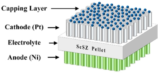
Fig. 2Schematic diagram of (a) sputtering system and (b) custom-made SOFC test station setup

Fig. 3Surface SEM images of PrOx capping layer with Pt thin films. (a)-(e) As-deposited samples with varying Pr concentrations: (a) Pure Pt, (b) Pr05, (c) Pr10, (d) Pr20, (e) Pr60. (f)-(j) Corresponding samples annealed at 500oC for 48 hours: (f) Pure Pt, (g) Pr05, (h) Pr10, (i) Pr20, (j) Pr60

Fig. 4EDS mapping images of Pr60 film annealed at 500℃ for 48 hours

Fig. 5Performances of LT-SOFCs (a) j-V-P curves and (b) Maximum power densities
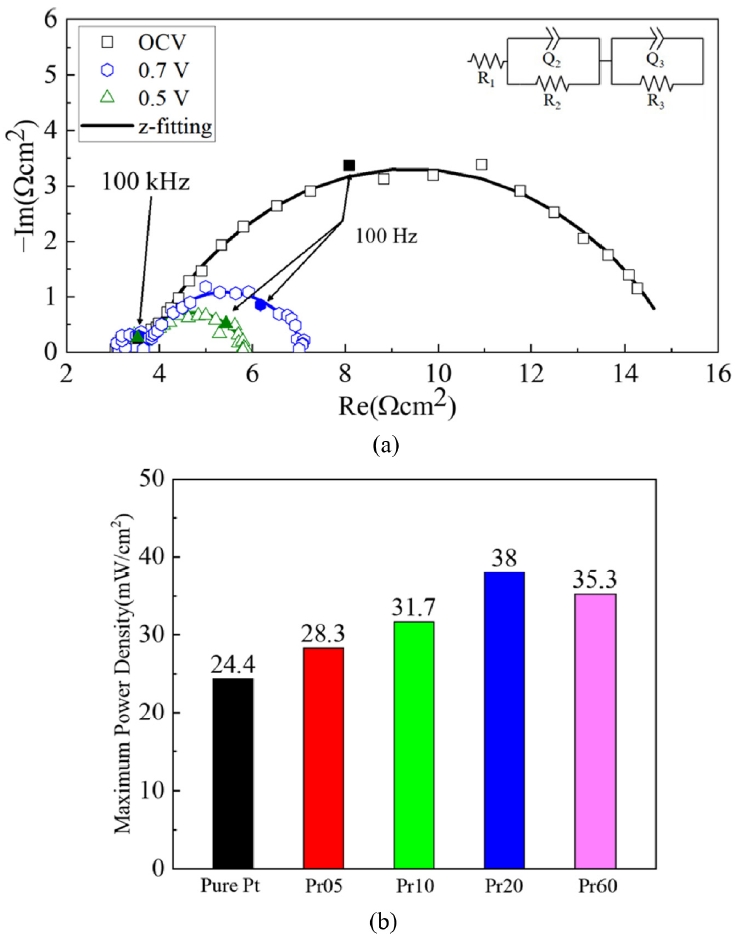
Fig. 6EIS results of LT-SOFCs (a) EIS measurements of the Pr20 case at OCV, 0.7V, and 0.5V (b) EIS results at 0.7 V for all cases
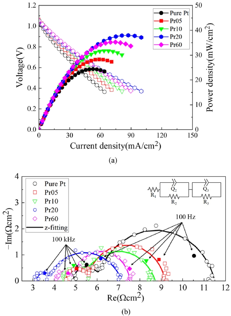
Fig. 7Short term stability test of LT-SOFCs at 500℃ (a) current densities at 0.5 V for 48 hours and (b) Comparison of initial and final current densities for 48 hours

Table 1Experimental parameters of electrodes fabrication
Table 1
|
Parameters |
Cathode (Pt) |
Anode (Ni) |
|
Thickness [nm] |
150 |
200 |
|
Pressure [mTorr] |
50 |
30 |
|
Gas flow [sccm] |
Ar 30 |
|
Deposition power [W] |
DC 100 |
|
Deposition temperature |
Room temperature |
Table 2Experimental parameters of PrOx capping layer fabrication
Table 2
|
Parameters |
Pr05 |
Pr10 |
Pr20 |
Pr60 |
|
Pressure [mTorr] |
5 |
|
Gas flow [sccm] |
Ar 24 + O2 6 |
|
Deposition power [W] |
RF 40 |
|
Deposition temperature |
Room temperature |
Table 3Ohmic resistance & Faradaic resistance of LT-SOFCs
Table 3
|
Parameters |
Pure Pt |
Pr05 |
Pr10 |
Pr20 |
Pr60 |
|
RΩ [Ωcm2] |
4.90 |
4.60 |
4.47 |
3.13 |
4.08 |
|
RF [Ωcm2] |
6.37 |
4.52 |
4.16 |
3.87 |
3.42 |
REFERENCES
- 1. O'hayre, R., LChaee, S.-W., Colella, W., Prinz, F. B., (2016), Fuel cell fundamentals, 3rd edition, John Wiley & Sons.
- 2. Cho, G. Y., Lee, Y. H., Yu, W., An, J., Cha, S. W., (2019), Optimization of Y2O3 dopant concentration of yttria stabilized zirconia thin film electrolyte prepared by plasma enhanced atomic layer deposition for high performance thin film solid oxide fuel cells, Energy, 173, 436-442.
- 3. Cho, G. Y., Lee, Y. H., Cha, S. W., (2014), Multi-component nano-composite electrode for SOFCs via thin film technique, Renewable Energy, 65, 130-136.
- 4. Kim, D. H., Bae, K., Choi, H. J., Shim, J. H., (2018), Ag surface-coated with nano-YSZ as an alternative to Pt catalyst for low-temperature solid oxide fuel cells, Journal of Alloys and Compounds, 769, 545-551.
- 5. Mat, Z. A., Nadaraja, S. K., Zakaria, Z., Hassan, S. H. A., Kar, Y. B., Tan, C. Y., Somalu, M. R., (2019), Fabrication and characterization of YSZ/SCSZ bilayer electrolyte via cold-isostatic pressing (CIP) method for intermediate temperature-solid oxide fuel cell (IT-SOFC) application, International Journal of Integrated Engineering, 11(7), 201-208.
- 6. Cho, G. Y., Kim, Y., Hong, S. W., Yu, W., Kim, Y.-B., Cha, S. W., (2018), Optimization of SCSZ/GDC bilayer thin film electrolyte for anodic aluminum oxide supported low temperature solid oxide fuel cells, Nanotechnology, 29(34), 345401.
- 7. Jeon, J.-W., Park, J.-G., Kim, G.-H., Lee, S.-H., Shin, J.-W., Cho, G.-Y., (2025), Analysis of electrochemical properties of LTSOFCs according to thickness of PrOx cathode interlayer, Sustainability, 17(4), 1403.
- 8. Steele, B. C., (2000), Appraisal of Ce1−yGdyO2−y/2 electrolytes for ITSOFC operation at 500oC, Solid State Ionics, 129(1-4), 95-110.
- 9. Adler, S. B., (2004), Factors governing oxygen reduction in solid oxide fuel cell cathodes, Chemical Reviews, 104(10), 4791-4844.
- 10. Nguyen, X. D., Lee, S. W., Kim, S. J., Park, J., Koo, B., Lee, S. H., Lee, S., Lim, H. T., Irvine, J. T., Shin, T. H., (2024), Boosting Electrochemical performance via extra-role of la-doped CeO2-δ interlayer for ‘oxygen provider’ at high-current SOFC operation, Advanced Science, 11(46), 2402348.
- 11. Sabarou, H., Darvish, S., Gupta, S., Singh, P., Zhong, Y., (2017), Thermodynamic assessment of the chemical stability of (La0.8Sr0.2)0.98CrxFe1−xO3±δ under oxygen transport membrane fabrication and operation conditions, Solid State Ionics, 310, 1-9.
- 12. Bai, J., Han, Z., Zhou, D., Zhu, X., Wang, N., Chen, R., He, J., Yan, W., (2023), Preparation of Pr2NiO4+δ-La0.6Sr0.4CoO3-δ as a high-performance cathode material for SOFC by an impregnation method, International Journal of Hydrogen Energy, 48(15), 6076-6087.
- 13. Jennings, P. C., Aleksandrov, H. A., Neyman, K. M., Johnston, R. L., (2014), A DFT study of oxygen dissociation on platinum based nanoparticles, Nanoscale, 6(2), 1153-1165.
- 14. He, F., Zhou, X., Liu, L., Sheng, Y., Jiang, X., Tang, Y., Dang, W., Du, J., Zhang, X., Niu, Y., (2024), Highperformance low-temperature solid oxide fuel cell with a Pt@C–Ni0.8Co0.15Al0.05LiO2−δ composite cathode, Energy & Fuels, 38(7), 6410-6419.
- 15. Seo, H. G., Choi, Y., Koo, B., Jang, A., Jung, W., (2016), Robust nano-architectured composite thin films for a low-temperature solid oxide fuel cell cathode, Journal of Materials Chemistry A, 4(24), 9394-9402.
- 16. Ryll, T., Galinski, H., Schlagenhauf, L., Elser, P., Rupp, J. L., Bieberle‐Hutter, A., Gauckler, L. J., (2011), Microscopic and nanoscopic three‐phase‐boundaries of platinum thin‐film electrodes on YSZ electrolyte, Advanced Functional Materials, 21(3), 565-572.
- 17. Vengrenovich, R., Ivanskii, B., Panko, I., Yarema, S., Kryvetskyi, V., Stasyk, M., (2014), Ostwald ripening of the platinum nanoparticles in the framework of the modified LSW theory, Journal of Nanomaterials, 2014(1), 821584.
- 18. Will, J., Denisov, N., Qin, S., Wu, M., Wang, Y., Kim, H., Karpstein, N., Dierner, M., Schmuki, P., Spiecker, E., (2025), Thermally-induced agglomeration tailors the stability of Pt SAs on Tio2 and use in photocatalytic H2 generation, Journal of Materials Chemistry A, 13(18), 13205-13217.
- 19. Wan, Q., Hu, S., Dai, J., Chen, C., Li, W.-X., (2018), First-principles kinetic study for ostwald ripening of late transition metals on Tio2 (110), The Journal of Physical Chemistry C, 123(2), 1160-1169.
- 20. Ji, S., Tanveer, W., (2020), Thickness determination of porous pt cathode thin film capped by atomic layer-deposited alumina for low-temperature solid oxide fuel cells, Applied Surface Science, 514, 145931.
- 21. Liu, K.-Y., Fan, L., Yu, C.-C., Su, P.-C., (2015), Thermal stability and performance enhancement of nano-porous platinum cathode in solid oxide fuel cells by nanoscale ZrO2 capping, Electrochemistry Communications, 56, 65-69.
- 22. Hong, S., Oh, S., Kim, H. J., Lim, Y., An, J., Kim, Y.-B., (2017), Enhanced thermal stability of a gadolinia-doped ceria capped metal electrode for durable low-temperature solid oxide fuel cells, Journal of The Electrochemical Society, 164(13), F1301.
- 23. Ferro, S., (2011), Physicochemical and electrical properties of praseodymium oxides, International Journal of Electrochemistry, 2011(1), 561204.
- 24. Shajahan, I., Ahn, J., Nair, P., Medisetti, S., Patil, S., Niveditha, V., Babu, G. U. B., Dasari, H. P., Lee, J.-H., (2018), Praseodymium doped ceria as electrolyte material for IT-SOFC applications, Materials Chemistry and Physics, 216, 136-142.
- 25. Ge, L., Sun, K., Gu, Y., Ni, Q., Huang, X., (2021), Boosting the performance of conventional air electrodes for solid oxide cells by in-situ loading of nano praseodymium oxide, Energy Conversion and Management, 249, 114873.
- 26. Sharma, R. K., Khamidy, N. I., Rapenne, L., Charlot, F., Moussaoui, H., Laurencin, J., Djurado, E., (2019), Highly efficient architectured Pr6O11 oxygen electrode for solid oxide fuel cell, Journal of Power Sources, 419, 171-180.
- 27. Bellakki, M. B., Shivakumara, C., Baidya, T., Prakash, A., Vasanthacharya, N., Hegde, M., (2008), Synthesis, structure and oxygen-storage capacity of Pr1−xZrxO2−δ and Pr1−x−yPdyZrxO2−δ, Materials Research Bulletin, 43(10), 2658-2667.
- 28. Jiang, N., Zhou, X., Jiang, Y.-F., Zhao, Z.-W., Ma, L.-B., Shen, C.-C., Liu, Y.-N., Yuan, C.-Z., Sahar, S., Xu, A.-W., (2018), Oxygen deficient Pr 6 O 11 nanorod supported palladium nanoparticles: Highly active nanocatalysts for styrene and 4-nitrophenol hydrogenation reactions, RSC Advances, 8(31), 17504-17510.
- 29. Zamudio-García, J., Caizán-Juanarena, L., dos Santos-Gómez, L., Porras-Vázquez, J. M., Losilla, E. R., Marrero-López, D., (2025), Enhanced thermal and electrochemical properties in La₀.₈Sr₀.₂MnO₃₋δ–Pr₆O₁₁ nanocomposite cathodes for solid oxide fuel cells, International Journal of Hydrogen Energy, 126, 552-561.
- 30. Cho, G. Y., Lee, Y. H., Hong, S. W., Bae, J., An, J., Kim, Y. B., Cha, S. W., (2015), High-performance thin film solid oxide fuel cells with scandia-stabilized zirconia (SCSZ) thin film electrolyte, International Journal of Hydrogen Energy, 40(45), 15704-15708.
- 31. Garg, R., Gonuguntla, S., Sk, S., Iqbal, M. S., Dada, A. O., Pal, U., Ahmadipour, M., (2024), Sputtering thin films: Materials, applications, challenges and future directions, Advances in Colloid and Interface Science, 330, 103203.
- 32. Galinski, H., Ryll, T., Elser, P., Rupp, J., Bieberle-Hütter, A., Gauckler, L., (2010), Agglomeration of pt thin films on dielectric substrates, Physical Review B—Condensed Matter and Materials Physics, 82(23), 235415.
- 33. Hartwig, C., Schweinar, K., Nicholls, R., Beeg, S., Schlögl, R., Greiner, M., (2021), Surface composition of agpd single-atom alloy catalyst in an oxidative environment, The Journal of Chemical Physics, 154(17), 174708.
- 34. Gadkari, P., Warren, A., Todi, R., Petrova, R., Coffey, K., (2005), Comparison of the agglomeration behavior of thin metallic films on SiO2, Journal of Vacuum Science & Technology A, 23(4), 1152-1161.
- 35. Murray, C. P., Mamyraimov, D., Ali, M., Downing, C., Povey, I. M., McCloskey, D., O’Regan, D. D., Donegan, J. F., (2023), Monolayer capping provides close to optimal resistance to laser dewetting of au films, ACS Applied Electronic Materials, 5(8), 4080-4093.
- 36. Zhang, J., Ricote, S., Hendriksen, P. V., Chen, Y., (2022), Advanced materials for thin‐film solid oxide fuel cells: Recent progress and challenges in boosting the device performance at low temperatures, Advanced Functional Materials, 32(22), 2111205.
- 37. Sharma, R., Djurado, E., (2018), An efficient hierarchical nanostructured pr 6 o 11 electrode for solid oxide fuel cells, Journal of Materials Chemistry A, 6(23), 10787-10802.
- 38. Pan, T.-M., Tsai, F.-J., Hsieh, C.-I., Wu, T.-W., (2007), Structural properties and electrical characteristics of praseodymium oxide gate dielectrics, Electrochemical and Solid-State Letters, 10(4), G21.
- 39. Han, W., Kim, J., Park, H.-H., (2019), Control of electrical conductivity of highly stacked zinc oxide nanocrystals by ultraviolet treatment, Scientific Reports, 9(1), 6244.
Biography
- Ji Woong Jeon
M.S. candidate in the Department of Mechanical Engineering, Dankook University. His research interests are fabrication and characterization of solid oxide fuel cells.
- Geon Hyeop Kim
M.S. candidate in the Department of Mechanical Engineering, Dankook University. His research interests are fabrication and characterization of solid oxide fuel cells.
- Hyeon Min Lee
M.S. candidate in the Department of Mechanical Engineering, Dankook University. His research interests are fabrication and characterization of solid oxide fuel cells.
- Jun Geon Park
M.S. candidate in the Department of Mechanical Engineering, Dankook University. His research interests are fuel cells, finite element method, deposition and characterization of thin films.
- Gu Young Cho
Associate Professor in the Department of Mechanical Engineering, Dankook University. His interests are the development of new and renewable energy devices and systems.