ABSTRACT
This study evaluates the load and moment characteristics of composite leaf springs used in the front suspension of a 4.0- ton gross vehicle weight (GVW) light commercial van through CarSim-based vehicle dynamics simulations. Carbon fiber composite (CFC), glass fiber composite (GFC), and hybrid composite (HC, carbon 20%: glass 80%) leaf springs were fabricated with identical geometry using a prepreg compression molding (PCM) process. Spring constants obtained from four-point bending tests were incorporated into the vehicle dynamics model. Dynamic responses were analyzed under flatroad driving, acceleration, braking, cornering, and speed bump conditions. The results indicate that the GFC leaf spring achieved a 61.5% weight reduction compared to a conventional steel spring while maintaining equivalent vertical load and roll moment responses. The HC exhibited improved roll suppression and pitch stability, whereas the CFC demonstrated excessively high stiffness, limiting its applicability to heavy-duty vehicles. Furthermore, the GFC maintained stable dynamic performance after low-velocity impact damage of 20 and 80 J, with stiffness remaining within ±5% of the steel reference. These findings confirm that composite leaf springs, particularly those made from glass fiber composites, provide a practical and durable alternative to steel leaf springs for light commercial vehicle suspension systems.
-
KEYWORDS: Vehicle dynamics, Composite leaf spring, Light commercial vehicles, Prepreg compression molding, Drop impact, Weight reduction
-
KEYWORDS: 차량동역학, 복합재 리프 스프링, 상용차량, PCM, 낙하충격, 경량화
1. Introduction
The automotive industry is facing increasing demands to comply with stringent environmental regulations by improving fuel efficiency and reducing greenhouse gas emissions. Vehicle lightweighting has emerged as one of the most effective approaches to address these challenges. Vehicle mass directly affects driving performance and fuel economy, and a weight reduction of approximately 10% has been reported to improve fuel efficiency by about 6–8% [
1,
2]. Consequently, extensive lightweight design research has been conducted for various vehicle components, including the body, chassis, powertrain, and suspension systems.
Steel multi-leaf springs are key suspension components widely used in commercial and off-road vehicles due to their simple structure and high load-carrying capacity, which have ensured long-term reliability. However, conventional JIS SUP7 (Si–Mn type) steel leaf springs suffer from several inherent limitations. Their multi-layer laminated structure results in relatively high mass, while interleaf friction induces hysteresis and NVH (noise, vibration, and harshness) issues [
3,
4]. These drawbacks degrade ride comfort, shorten fatigue life, and increase energy loss, making it difficult to satisfy future requirements for improved fuel efficiency.
Fiber-reinforced plastic (FRP) leaf springs have recently attracted significant attention as an alternative to conventional steel leaf springs. Composite materials exhibit high specific strength and specific stiffness, making them suitable for lightweight structural applications. In addition, composites provide superior corrosion resistance, fatigue resistance, vibration damping capability, and design flexibility compared to metallic materials [
5-
7]. As a result, composite materials have been increasingly adopted in various transportation systems, including aircraft, ships, and railway vehicles, and their application has recently expanded to automotive components such as body panels, axles, and suspension parts [
8,
9].
Composite leaf springs offer considerable potential for weight reduction, achieving approximately 50–70% lower mass than steel leaf springs while maintaining comparable stiffness and strength through optimized laminate design and forming processes [
10,
11]. When applied to small commercial vehicles, composite leaf springs can provide several benefits. First, vehicle weight reduction contributes to improved fuel efficiency and reduced carbon dioxide emissions. Second, a decrease in unsprung mass enhances ride comfort and handling stability. Third, the excellent fatigue resistance of composite materials improves durability and service life [
12].
Despite these advantages, several technical challenges remain in the commercialization of composite leaf springs. The anisotropic nature of composite materials leads to nonlinear and loaddependent stress distributions that are difficult to predict accurately [
13]. Composite structures are also susceptible to damage accumulation caused by low-velocity impacts and cyclic loading, which may result in stiffness degradation and reduced structural stability [
4]. Furthermore, from a manufacturing perspective, ensuring quality uniformity and optimizing laminate configurations during the prepreg compression molding (PCM) process remain critical issues [
14].
Recent studies have increasingly employed CAE (Computer-Aided Engineering)-based analytical approaches to overcome these challenges. The combined application of multi-body dynamics (MBD) and the finite element method (FEM) enables accurate simulation of real vehicle driving conditions and precise prediction of load characteristics. Moon et al. [
16] analyzed hysteresis behavior and dynamic stress in tapered leaf springs using a flexible multi-body dynamics model. Lee et al. [
17] evaluated the vehicle dynamic behavior of composite leaf springs using CarSim and confirmed their feasibility for practical vehicle applications.
Domestic research efforts have also focused on vehicle lightweighting and performance improvement through the application of composite leaf springs. Song et al. [
18] designed a composite transverse leaf spring with integrated link functionality and achieved approximately 40% weight reduction and improved vibration damping performance compared to conventional multilink suspension systems. Park et al. [
19] applied a GFRP (glass fiber-reinforced plastic) leaf spring to a CTBA (coupled torsion beam axle) suspension system and demonstrated approximately 30% weight reduction and improved vehicle dynamic performance relative to steel coil springs.
This study applies transverse-type composite leaf springs (carbon fiber, glass fiber, and hybrid carbon/glass) to the front axle of a 4.0-ton gross vehicle weight (GVW) small passenger van. Vehicle dynamic analyses are conducted under various driving conditions using CarSim to evaluate load and torque characteristics. The objective of this study is to assess the lightweighting effectiveness of composite leaf springs while maintaining vehicle dynamic performance, thereby providing fundamental data for the optimal design and durability evaluation of suspension systems in future small commercial vehicles.
2. Materials
2.1 Composite Leaf Spring
The composite leaf springs investigated in this study were fabricated using a PCM process. A 125°C thermosetting epoxy prepreg (Toray SKYFLEX K51), listed in
Table 1, was selected as the constituent material. Material properties were evaluated in accordance with relevant ASTM standards. Prior to the fabrication process, thermal and mechanical characteristics were examined through differential scanning calorimetry (DSC) and dynamic mechanical analysis (DMA).
The DSC tests were conducted following ASTM D3418 to determine the onset of cure, end of cure, thermal stability, phase transitions (melting point and glass transition temperature), and total exothermic heat under different heating rates. In addition, isothermal DSC tests were performed to characterize the exothermic behavior and reaction time at specific temperature conditions [
20]. The glass transition temperature (
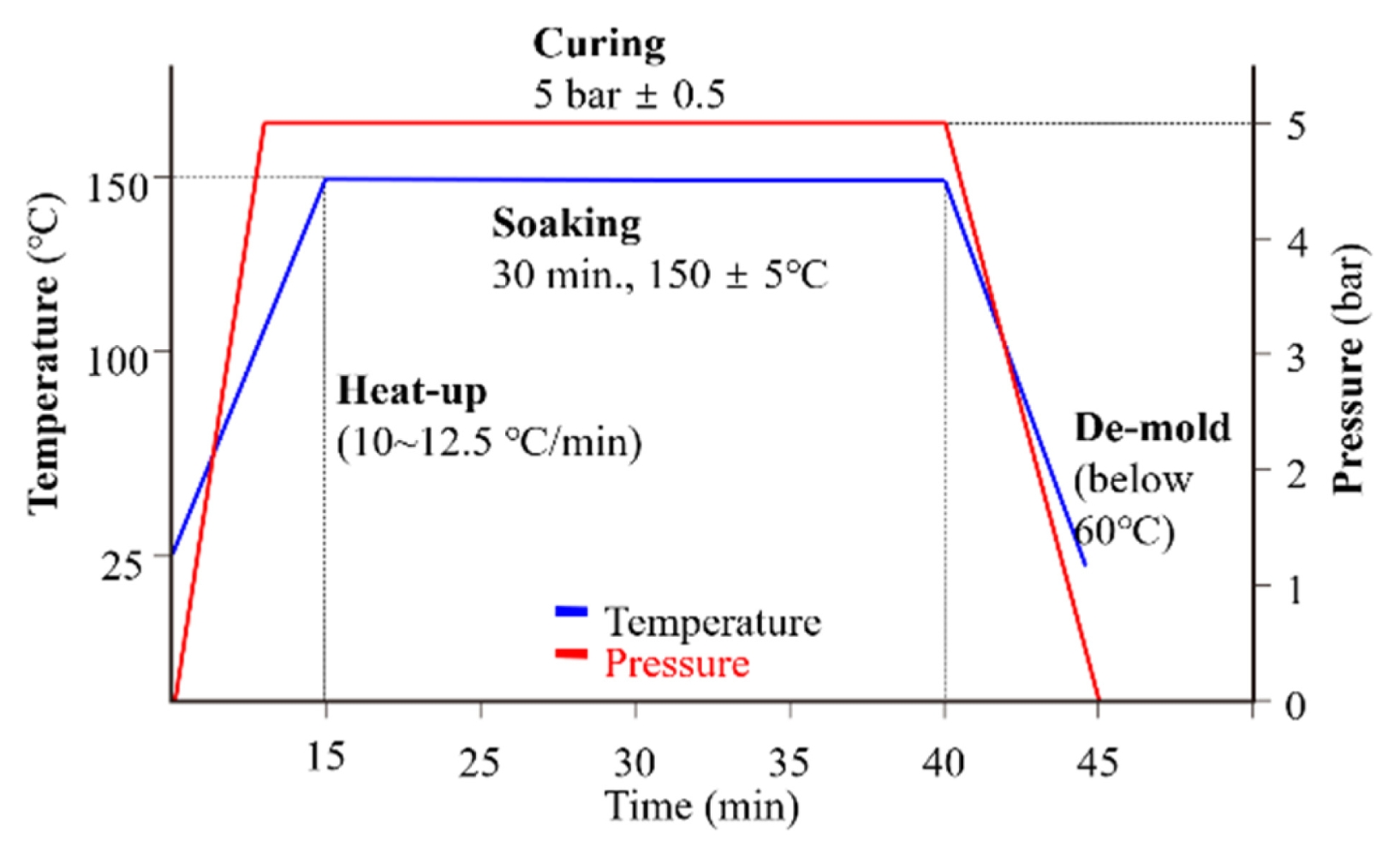
Tg), evaluated based on the tanδ peak according to ASTM D3418, was identified as 145.2°C. Based on these results, the optimal curing temperature and curing time for the PCM process were determined, and the final molding cycle conditions were established as shown in
Fig. 1.
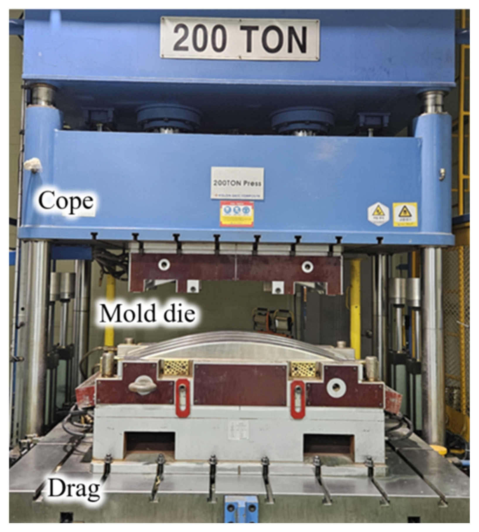
Prepreg sheets were cut and stacked into 68 plies by considering the target thickness and stacking sequence. The main curing process was carried out using a compression molding apparatus, as illustrated in
Fig. 2. As shown in
Fig. 1, the main curing cycle was set to 150°C under a pressure of 5 bar for 30 min. The temperature ramp during the main curing stage was carefully controlled to regulate resin gelation. Subsequently, a post-curing process was conducted at 145°C for 60 min to relieve residual stress and to secure sufficient mechanical stiffness.
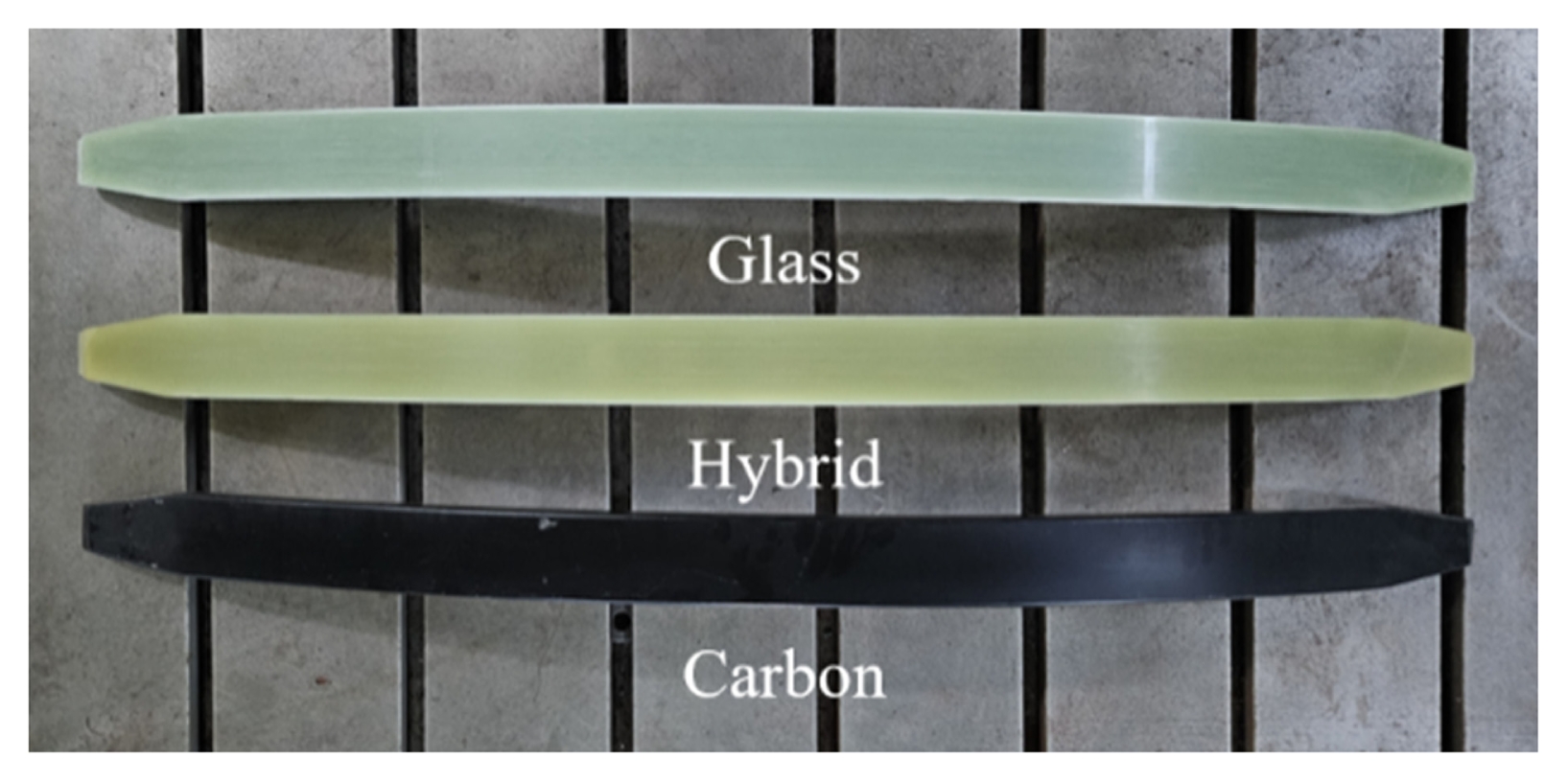
The composite leaf springs fabricated through this process exhibited uniform geometry and satisfactory surface quality, as shown in
Fig. 3. The specimens were prepared for spring constant (
K) measurement. All specimens were manufactured using unidirectional laminates. Three types of composite materials were considered: carbon fiber composite (CFC), glass fiber composite (GFC), and a hybrid composite (HC) consisting of carbon and glass fibers with a stacking ratio of 2 : 8 ([GFC]
18/[CFC]
8/[GFC]
18/[CFC]
8/[GFC]
18). The material properties of each composite system are summarized in
Table 1.
Prior to the vehicle dynamics analysis, the spring constants of the composite leaf springs considered in this study were compared with those of a conventional steel leaf spring (JIS SUP7), which is widely used in 4.0-ton GVW small passenger vans. The reference steel leaf spring exhibits a spring constant of 295 N/mm and a mass of 15.5 kg. To ensure a fair comparison, all composite leaf springs were fabricated with identical geometry and dimensions of 1,350 mm in length, 74 mm in width, and 30 mm in thickness.
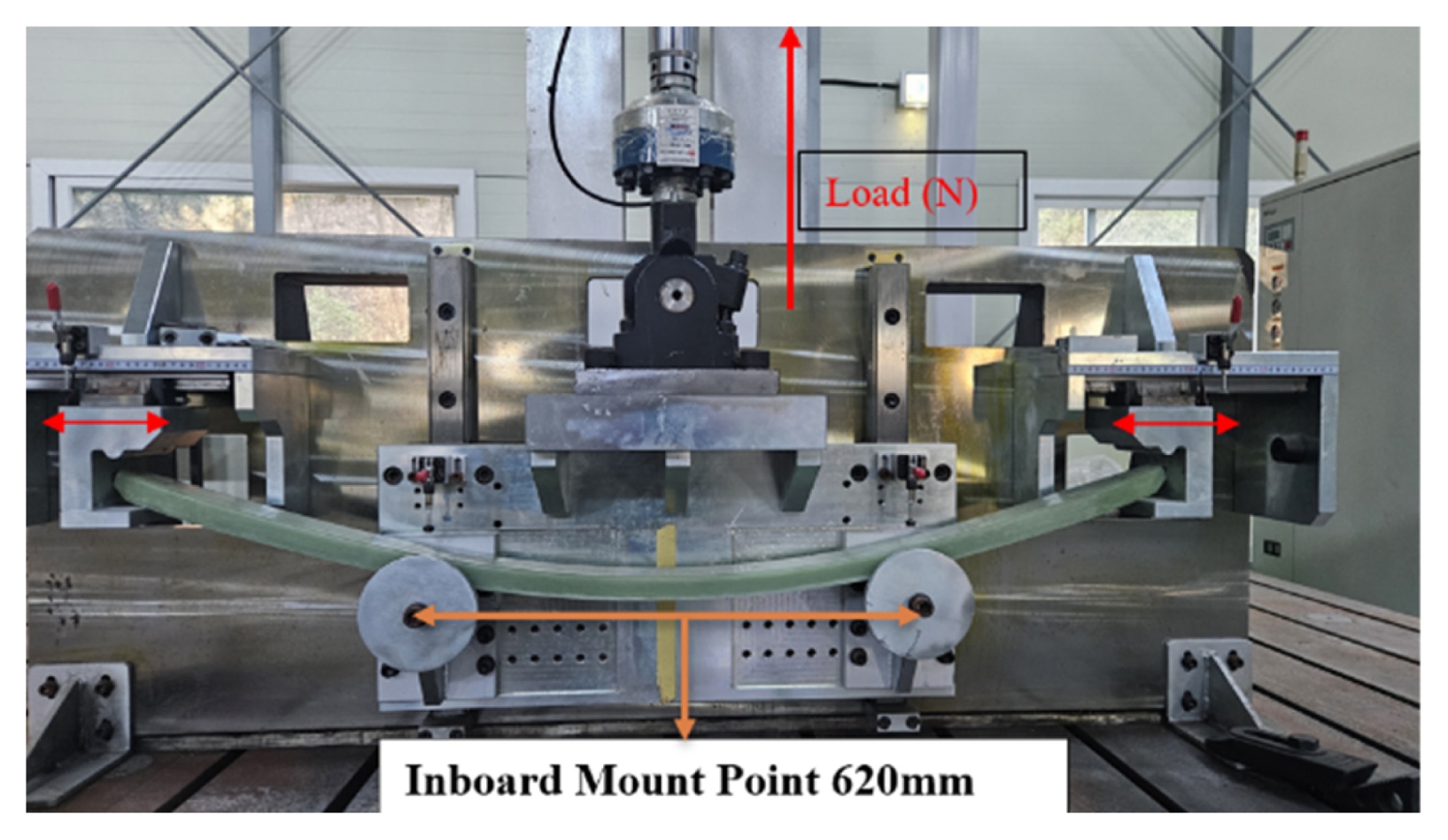
The spring constant of each composite leaf spring was measured using a dedicated four-point bending test apparatus, as shown in
Fig. 4. The test results indicate that the GFC leaf spring exhibited a spring constant of 297 N/mm, which is nearly identical to that of the steel leaf spring. This result confirms that the application of a composite material can achieve approximately 61% weight reduction without degrading the spring performance compared to the conventional steel counterpart.
The HC leaf spring showed a spring constant of 315 N/mm, representing an increase of approximately 7% relative to the reference steel leaf spring and a slightly higher stiffness than that of the GFC leaf spring. This improvement can be attributed to the local reinforcement effect of carbon fibers. The HC therefore provides a balanced combination of ride comfort retention, characteristic of GFC leaf springs, and enhanced stiffness associated with CFC leaf springs.
The CFC leaf spring exhibited a spring constant of 875 N/mm, which is more than three times higher than that of the steel leaf spring. Although this result indicates excellent load-carrying capability, such excessive stiffness is expected to cause degraded ride comfort and increased vibration transmission. Consequently, the CFC leaf spring is considered more suitable for high-load applications, such as heavy-duty commercial vehicles or specialpurpose vehicles, rather than small passenger vans.
The impact durability of the GFC leaf spring was evaluated using a drop-weight impact test, as shown in
Fig. 5. A hemispherical impactor with a diameter of 0.5 inch was used. Impact loading was applied to the center of the lower surface of the GFC leaf spring using a drop-weight impact testing machine (HIT600F, Zwick Roell).
The impact tests were conducted in accordance with ASTM D7136. The specimens were fixed using a toggle clamp system and positioned on a rectangular hollow support with dimensions of 75 mm × 125 mm, centered beneath the specimen [
21]. Each test was designed to generate a single impact at the center of the specimen, while rebound was carefully controlled to prevent secondary impacts.
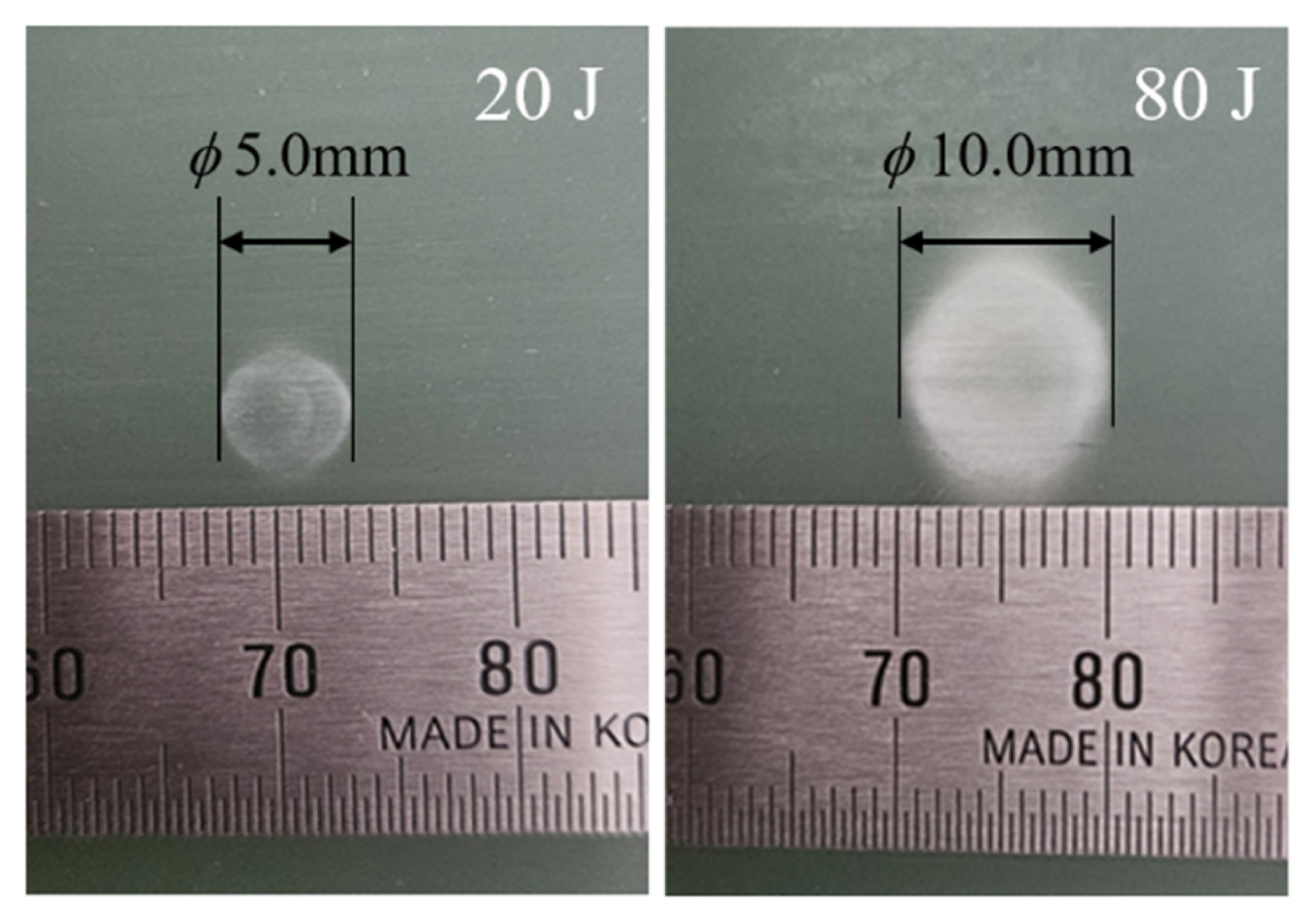
An impact energy of 20 J corresponds to the collision of approximately 80 g of road gravel at a vehicle speed of 80 km/h. An impact energy of 80 J represents the maximum impact condition, assuming that an external object of identical mass collides at the same speed. As shown in
Fig. 6, the damage diameter was approximately 5 mm at 20 J and increased to approximately 10 mm at 80 J.
The residual spring constant was remeasured through a fourpoint bending test after impact. The spring constants after 20 and 80 J impacts were 284 and 280 N/mm, respectively. These values correspond to stiffness retention levels of approximately 95–96% relative to the reference steel leaf spring. Although impact-induced damage caused a slight reduction in spring constant, the measured values remained within the manufacturer’s allowable tolerance range of 295 N/mm ± 5%.
These results indicate that the GFC leaf spring maintains structural integrity and stable mechanical performance under lowvelocity impact conditions, while also achieving significant weight reduction.
3. Vehicle Dynamics Analysis
3.1 CarSim Simulation Environment
This study focuses on an H-manufacturer small passenger van (Model S) with a GVW of 4.0 tons. The vehicle model was developed based on the Large European Van template provided in CarSim, with modifications to reflect the actual vehicle specifications and chassis configuration. Both the front and rear axles were modeled as solid axles, and a leaf spring suspension system was applied to the front axle.
Five driving conditions were considered in the vehicle dynamics simulations: (i) straight-line driving on a flat road, (ii) acceleration, (iii) braking, (iv) cornering with a turning radius of 50 m at a vehicle speed of 60 km/h, and (v) traversal of a speed bump with a height of 3.5 cm and a width of 40 cm at a vehicle speed of 120 km/h.
To represent the front leaf spring behavior, front suspension springs and dampers were defined in the CarSim model. The dampers were assumed to be mounted at both ends of the leaf spring, corresponding to the left and right mounting points. Accordingly, the distance between the left and right dampers was set to 1,100 mm. Under this configuration, spring forces were assumed to act on the fixed solid axle at each mounting point of the leaf spring. The distance between the left and right mounting points was set to 620 mm, and the same value was applied to the spacing between the two springs.
Depending on the leaf spring material, six different spring constant values obtained from the experiments in Section 2 were applied in the simulations. These included composite leaf springs (CFC, HC, GFC, and two impact-damaged GFC cases) and a conventional steel leaf spring.
The output signals extracted from the vehicle dynamics simulations consisted of forces (
Fx,
Fy,
Fz) and moments (
Mx,
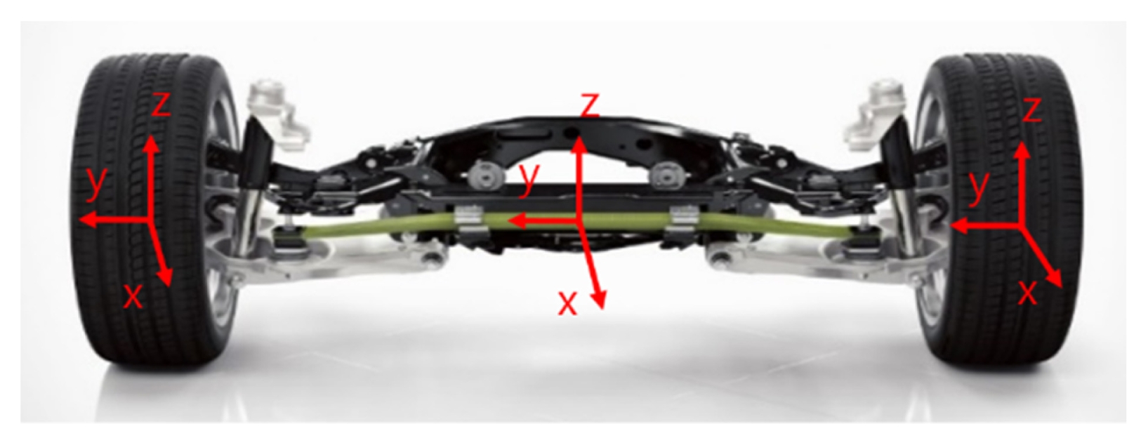
Mz), which were defined with respect to the leaf spring center coordinate system shown in
Fig. 7. The longitudinal force
Fx was calculated by integrating the
x-direction forces acting at the front left and right wheel centers and the mounting points. The lateral force
Fy was calculated from the
y-direction forces acting at the front wheel centers. The vertical force
Fz was derived from the spring forces acting at the left and right mounting points.
The moment about the
x-axis,
Mx, corresponds to the roll moment of the front leaf spring. The moment about the
y-axis, My, was assumed to be zero. The moment about the
z-axis,
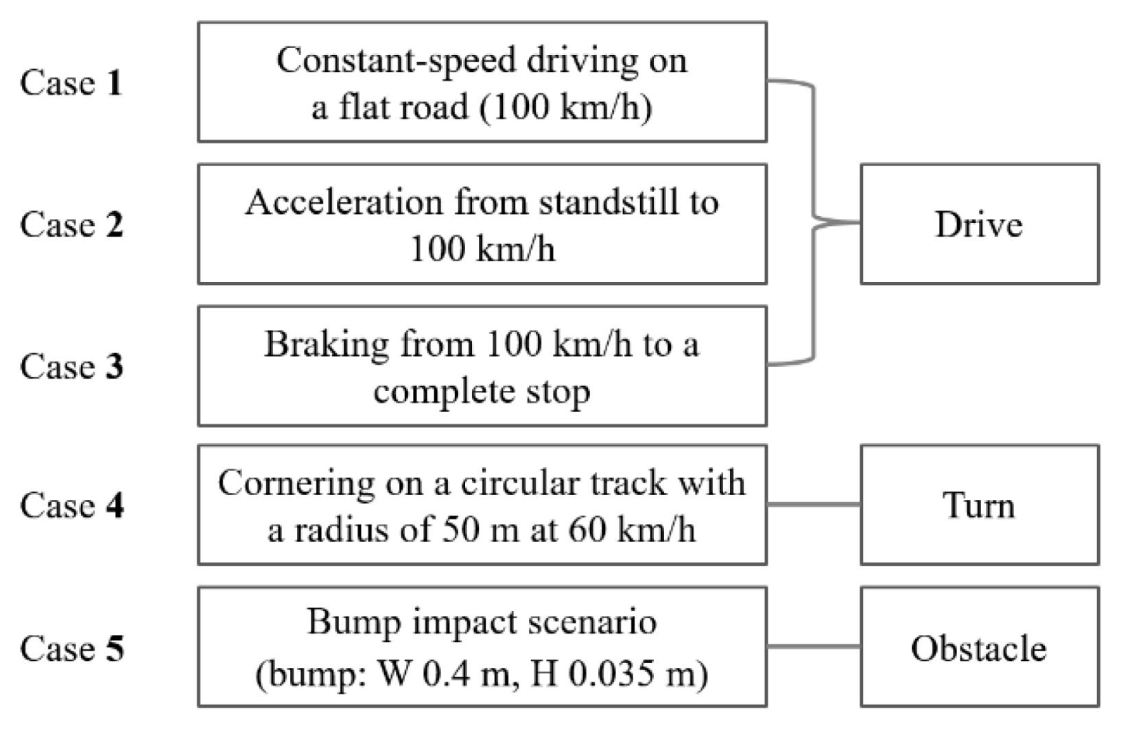
Mz, was calculated by integrating the z-direction forces acting at the front wheel centers and the mounting points. The driving cases considered in this study are summarized in
Fig. 8.
3.2.1 Case 1: Constant-speed Driving on a Flat Road (100 km/h)
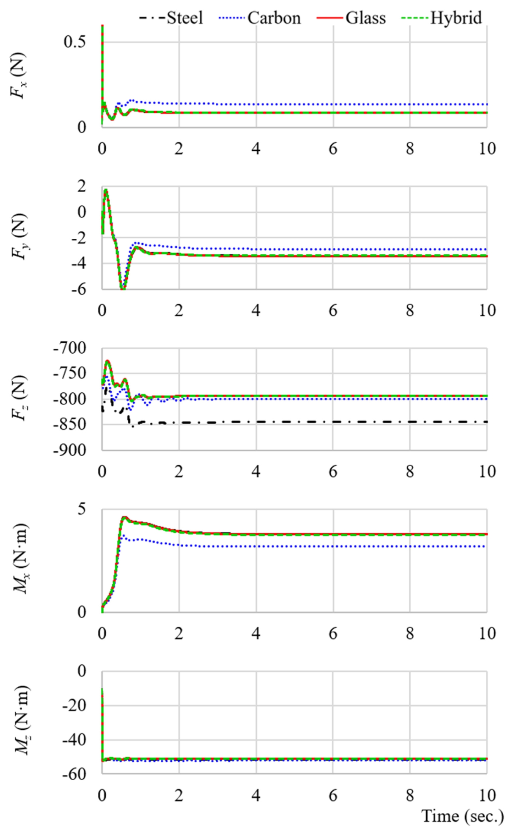
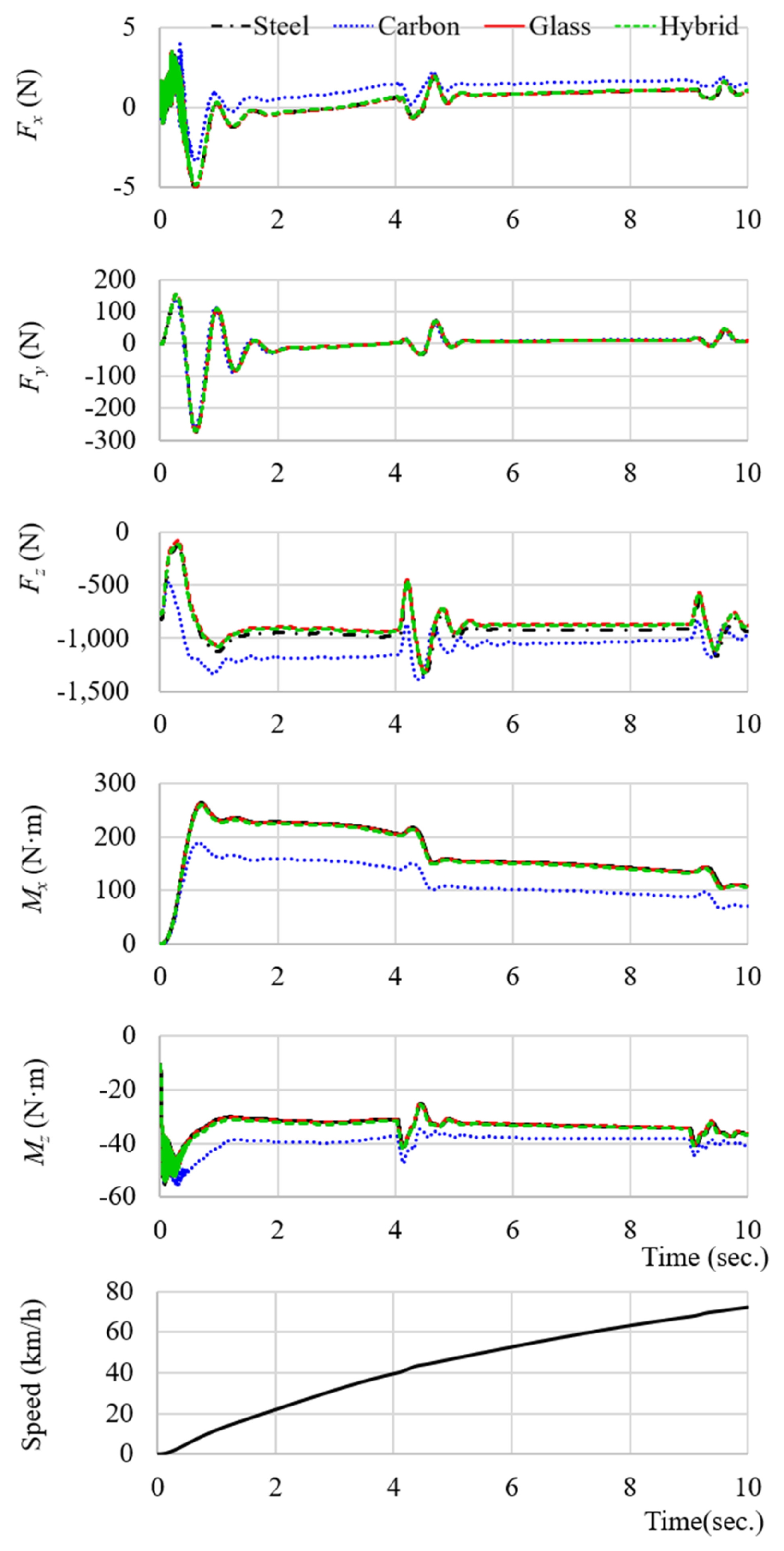
The CarSim simulation results, shown in
Fig. 9, indicate that the vertical load (
Fz) acting on the leaf spring, as well as the forces and moments along each axis, remained stable and nearly constant during steady-state driving. A comparison among different materials reveals that the magnitude of the vertical load increased in the order of CFC, HC, GFC, GFC with 20 J impact damage, and GFC with 80 J impact damage.
This trend is consistent with the tendency of materials with higher spring constants to generate larger restoring forces. However, the steel leaf spring exhibits a relatively higher vertical load despite having a lower spring constant than the carbon composite. This behavior is attributed to its larger unsprung mass, which is approximately 10.5 kg higher than that of the composite leaf springs, leading to increased vertical load under straight-line constant-speed driving conditions (Case 1).
The results also show that an increase in spring stiffness led to a reduction in the roll moment (Mx). This behavior indicates an enhanced capability to suppress lateral body roll as the stiffness of the leaf spring increases.
The GFC leaf spring exhibited a load distribution nearly identical to that of the steel leaf spring while achieving a weight reduction of approximately 61.5%. In addition, the response to road input was faster, resulting in stable vehicle behavior. In contrast, the CFC leaf spring, which has excessively high stiffness (875 N/mm), showed reduced load fluctuation but increased vehicle body acceleration, suggesting potential degradation in ride comfort. The HC leaf spring demonstrated a balanced response between roll suppression performance and ride comfort.
3.2.2 Case 2: Acceleration from Standstill to 100 km/h
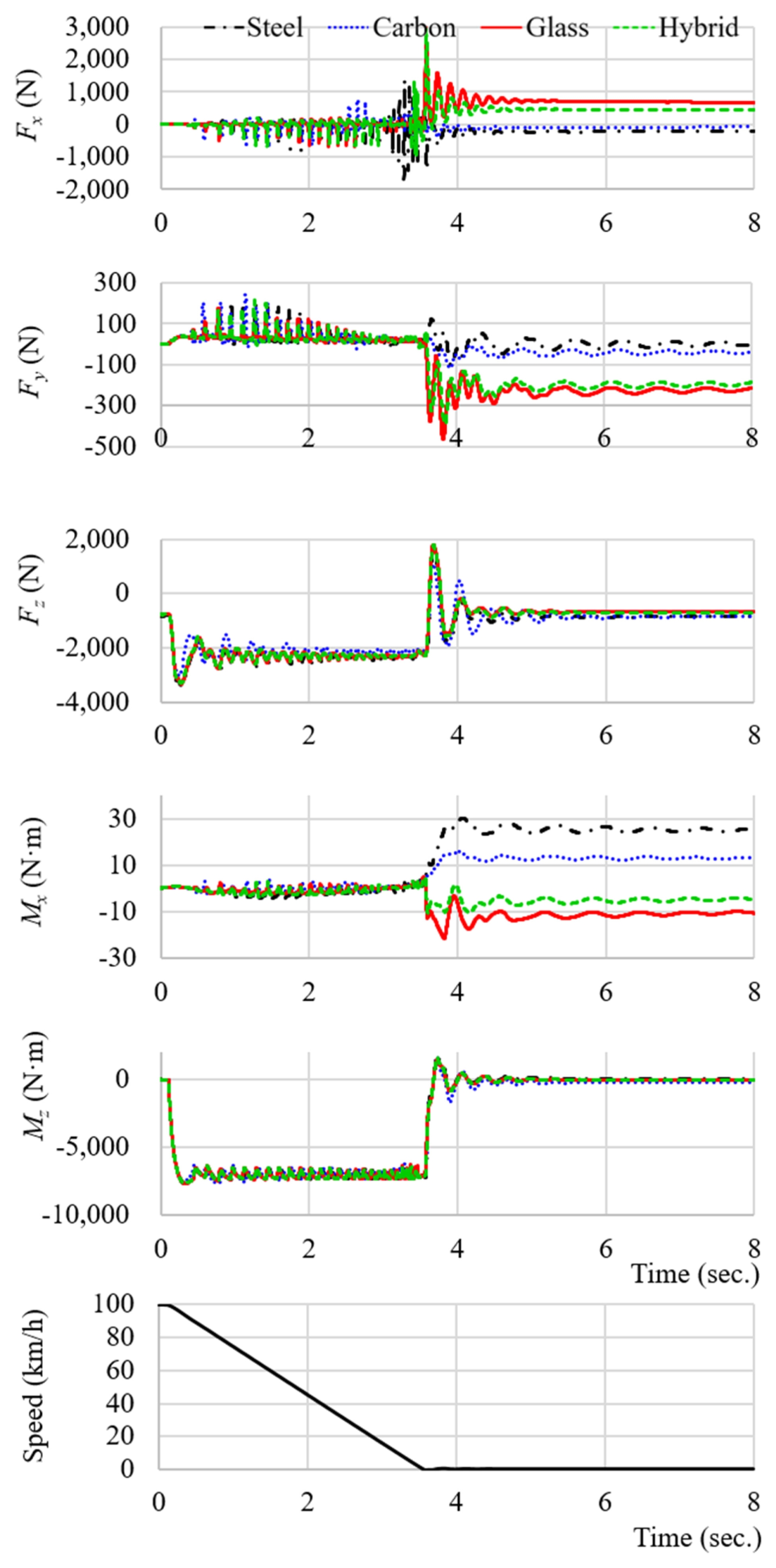
The simulation results shown in
Fig. 10 indicate that longitudinal load transfer toward the rear axle caused a reduction in the vertical load (
Fz) acting on the front axle. As a result, the restoring force and damping response characteristics of the front leaf spring became more pronounced during the acceleration phase. Materials with higher spring stiffness exhibited a smaller reduction in front-axle vertical load, leading to reduced pitch displacement of the vehicle body.
The CFC leaf spring showed the strongest restoring force, effectively suppressing the nose-up behavior during acceleration. However, excessive stiffness resulted in increased vibration during the initial acceleration phase. The HC leaf spring, which has approximately 7% higher stiffness than the steel leaf spring, simultaneously improved suppression of front-end dive and overall acceleration stability. In contrast, the GFC leaf spring exhibited an Fz variation trend nearly identical to that of the steel leaf spring, indicating comparable ride comfort and vehicle posture stability during acceleration.
3.2.3 Case 3: Braking from 100 km/h to Standstill
During braking, longitudinal load transfer toward the front axle caused an increase in the vertical load (Fz) acting on the front axle, accompanied by an increase in vehicle pitch motion. Materials with higher spring stiffness exhibited a greater suppression of nosedive behavior, resulting in a reduced variation in front-axle load distribution.
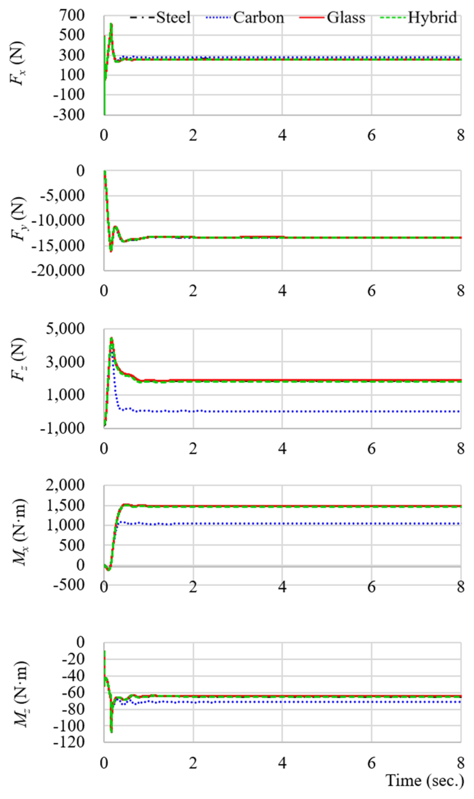
The simulation results shown in
Fig. 11 indicate that the CFC leaf spring exhibited the lowest peak
Fz during braking, while minimizing changes in vehicle pitch angle. This behavior demonstrates the most effective nose-dive suppression performance among the evaluated materials. The HC leaf spring showed a slightly lower
Fz increase rate than the steel leaf spring, while maintaining excellent braking stability and response characteristics. The GFC leaf spring exhibited a load distribution nearly identical to that of the steel leaf spring. Owing to its weight reduction, the spring restoration response was faster, allowing stable vehicle posture to be maintained during braking.
3.2.4 Case 4: Cornering on a Circular Track (Radius 50 m, 60 km/h)
During cornering, lateral load transfer induced by centrifugal force increased the vertical load on the outer wheel while reducing that on the inner wheel, resulting in the generation of a roll moment (Mx). As the spring stiffness increased, the roll angle decreased and the variation range of Mx was reduced.
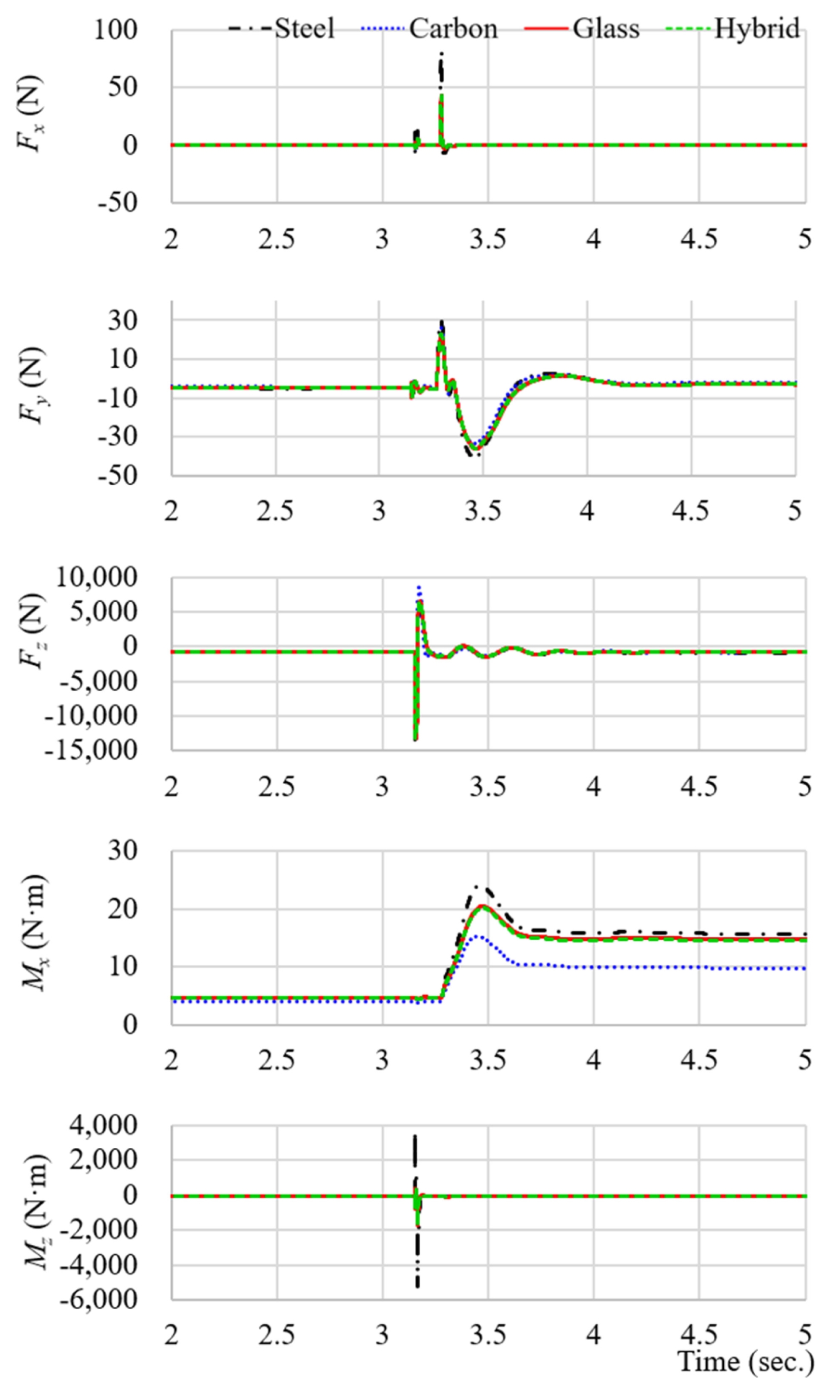
The simulation results presented in
Fig. 12 show that the CFC leaf spring exhibited the smallest increase in outer-wheel vertical load (
Fz), indicating the most effective roll suppression performance. The HC leaf spring demonstrated higher roll stiffness than the GFC leaf spring, leading to improved cornering stability. In contrast, the GFC leaf spring maintained an
Fz –
Mx relationship similar to that of the steel leaf spring, providing a favorable balance between handling stability and ride comfort.
3.2.5 Case 5: Speed Bump Crossing (Height 3.5 cm, Width 40 cm, Vehicle Speed 120 km/h)
When the vehicle encounters the speed bump, severe transient vibrations occur in all force and moment components acting on the leaf spring. As the vehicle passes over the bump, these vibrations are rapidly attenuated due to the damping characteristics of the suspension system. Consistent with the trends observed in the previous cases, materials with higher spring stiffness—namely carbon fiber composite (CFC), hybrid composite (HC), glass fiber composite (GFC), and steel—exhibited progressively smaller roll moment (Mx) responses.
Fig. 13 presents the simulation results at a vehicle speed of 120 km/h. As vehicle speed increases, the impact energy generated during contact with the speed bump increases accordingly, resulting in a larger roll moment
Mx acting on the leaf spring. In this case, particular attention was paid to the lateral force and impact energy transmitted to the leaf spring during the bump crossing event.
The calculated impact energies at vehicle speeds of 60, 80, 100, and 120 km/h were 11.1, 20, 31, and 45 J, respectively, assuming a stationary speed bump (relative speed = 0). These values represent realistic impact conditions that can occur in actual road environments and provide a rational basis for evaluating the dynamic durability and stability of the leaf spring under high-speed transient loading.
Table 3 summarizes the peak vertical load and peak roll moment for each composite configuration. The peak vertical load was maximized during the speed bump crossing condition due to the transient impact input, while the peak roll moment occurred during cornering, where sustained lateral acceleration dominated the vehicle response.
4. Conclusions
In this study, composite leaf springs applicable to the front suspension of a GVW 4.0-ton class light commercial van were designed and manufactured. Vehicle dynamic simulations based on CarSim were conducted to quantitatively evaluate the effects of material-dependent spring constants on load and moment characteristics. The major conclusions obtained from this study are summarized as follows.
A. Manufacturing and Material Characterization of Composite Leaf Springs
CFC, GFC, and HC leaf springs fabricated using the PCM process exhibited uniform geometry and consistent material properties. In particular, the GFC showed a tensile strength of 835 MPa and an elastic modulus of 88 GPa, achieving a weight reduction of 61.5% compared to SUP7 steel while maintaining an equivalent spring constant of 297 N/mm.
B. Spring Constant Evaluation Using Four-point Bending Tests
The CFC exhibited approximately three times higher stiffness than the conventional steel leaf spring, while the HC showed an increase in the spring constant of approximately 7%. In contrast, the GFC maintained a spring constant nearly identical to that of steel, indicating that it can serve as a direct and practical replacement for steel leaf springs in front suspension systems.
C. Vehicle Dynamic Simulation Results based on CarSim
Under flat-road and acceleration conditions (Cases 1–2), the GFC demonstrated vehicle response characteristics and ride comfort comparable to those of the steel leaf spring. During braking and cornering conditions (Cases 3–4), the HC exhibited superior roll suppression and pitch stability, while the GFC maintained Fz responses within ±5% of the steel reference.
In the speed-bump driving condition (Case 5), the GFC retained spring constants of 284 N/mm and 280 N/mm after impact damage of 20 and 80 J, respectively, which remained within the acceptable range of the steel reference (295 N/mm ±5%). These results indicate that the reduction in spring stiffness after impact damage was limited to within 5%, demonstrating stable dynamic behavior and sufficient impact durability even under low-velocity impact conditions.
D. Overall Assessment
Overall, the GFC was identified as the most practical alternative to steel leaf springs, providing equivalent stiffness and impact resistance while enabling significant weight reduction of the suspension system. The HC was evaluated as a balanced composite material that simultaneously enhances roll suppression and handling stability. The CFC, due to its excessively high stiffness, is more suitable for heavy-duty commercial or specialpurpose vehicles operating under high-load and high-speed conditions.
The results of this study experimentally demonstrate the feasibility of applying composite leaf springs to light commercial vehicles. Furthermore, when combined with FEM-based structural optimization and advanced vehicle dynamics analyses, the proposed approach is expected to contribute significantly to weight reduction and performance enhancement of automotive suspension systems.
Future studies will extend the present work by investigating the variation of spring stiffness as a function of impact damage severity, including BVID, VID, and extreme damage conditions. The relationship between damage-induced stiffness degradation and vehicle dynamic responses—such as vertical load variation, roll moment, and ride stability—will be systematically evaluated using combined experimental testing and vehicle dynamics simulations. Through this approach, damage-tolerant performance criteria for composite leaf springs can be established, providing a rational basis for durability assessment and design optimization of suspension systems for light commercial vehicles.
FOOTNOTES
-
ACKNOWLEDGEMENT
The authors sincerely acknowledge Samsong Tech Co., Ltd. and its members for their generous support and cooperation in this research.
Fig. 1Molding process for specimens (one-step cure cycle)
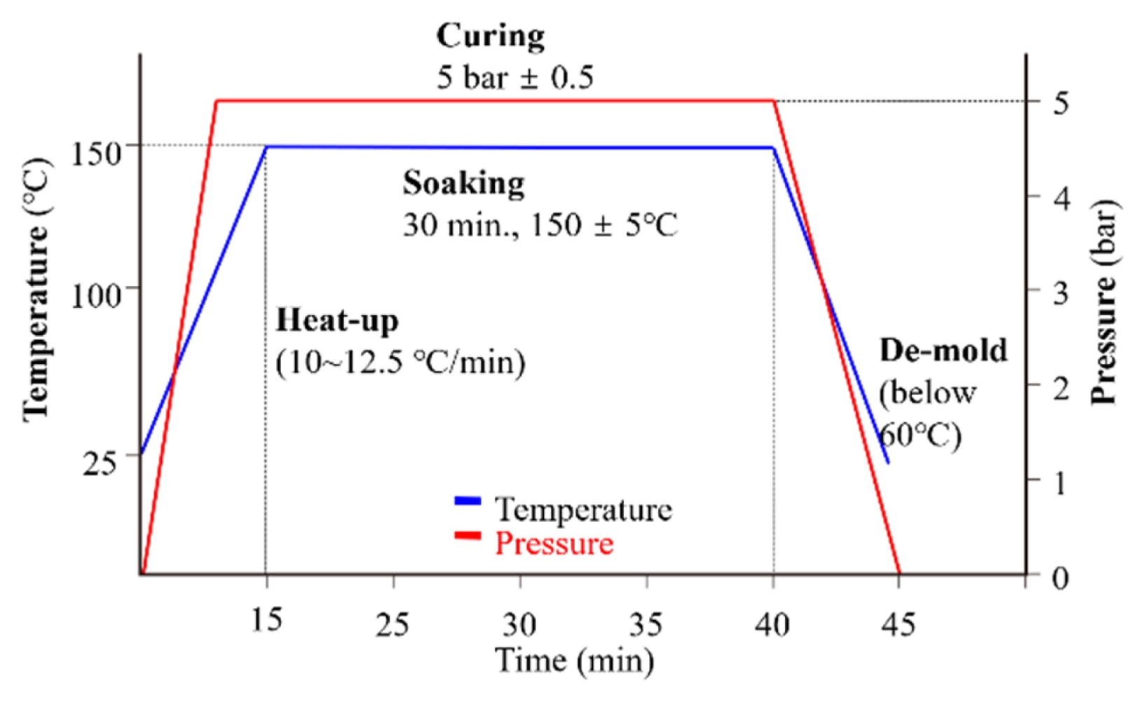
Fig. 2A set up of PCM process to manufacture leaf spring
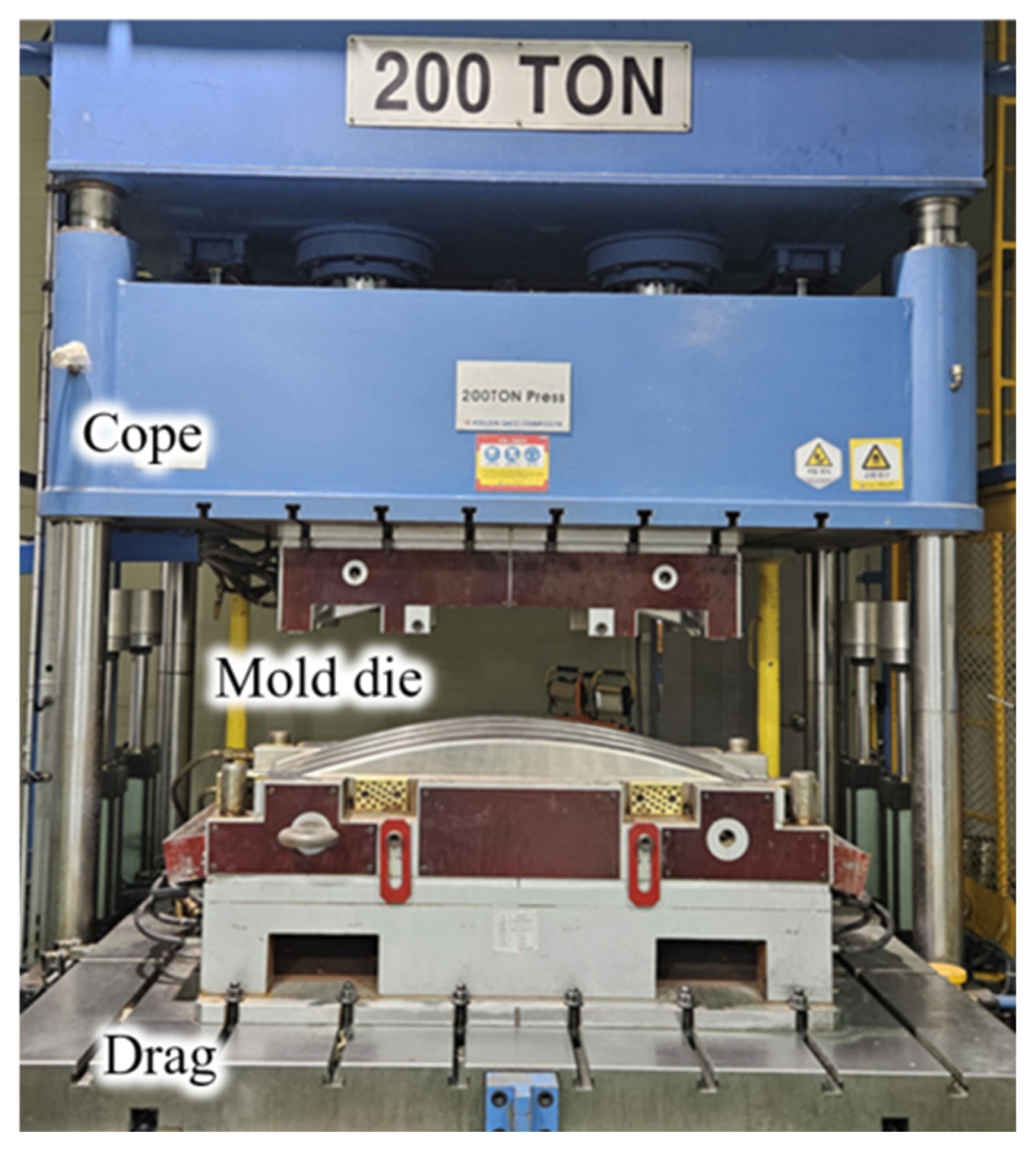
Fig. 3Fabricated composite leaf springs
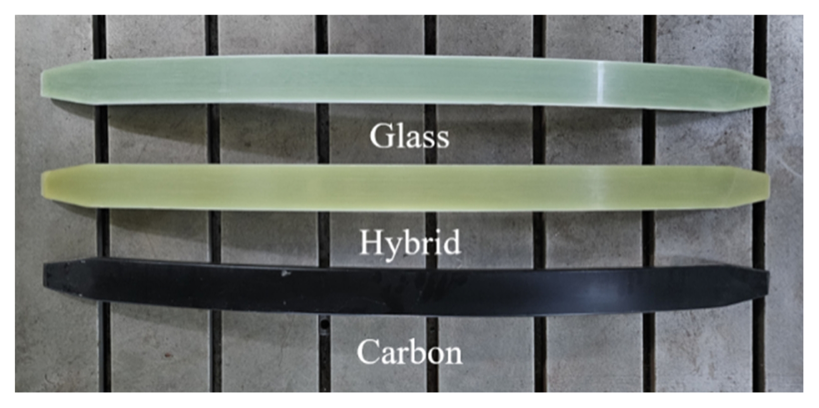
Fig. 4Set up of 4-point Bending test for composite leaf spring
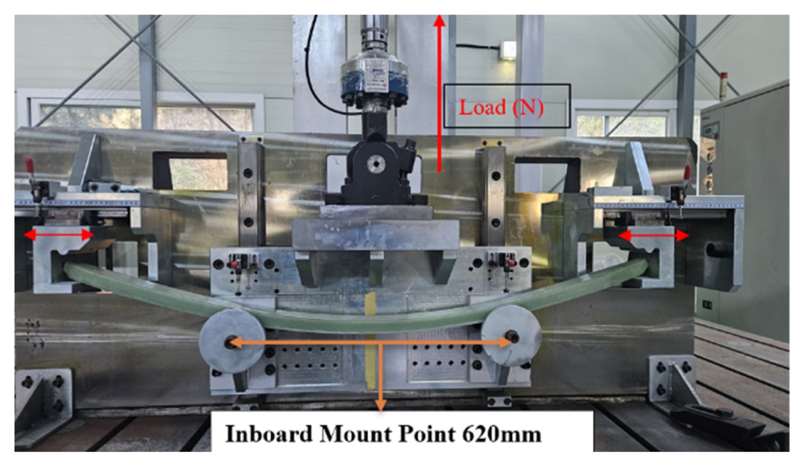
Fig. 5setup for drop impact test for composite leaf spring
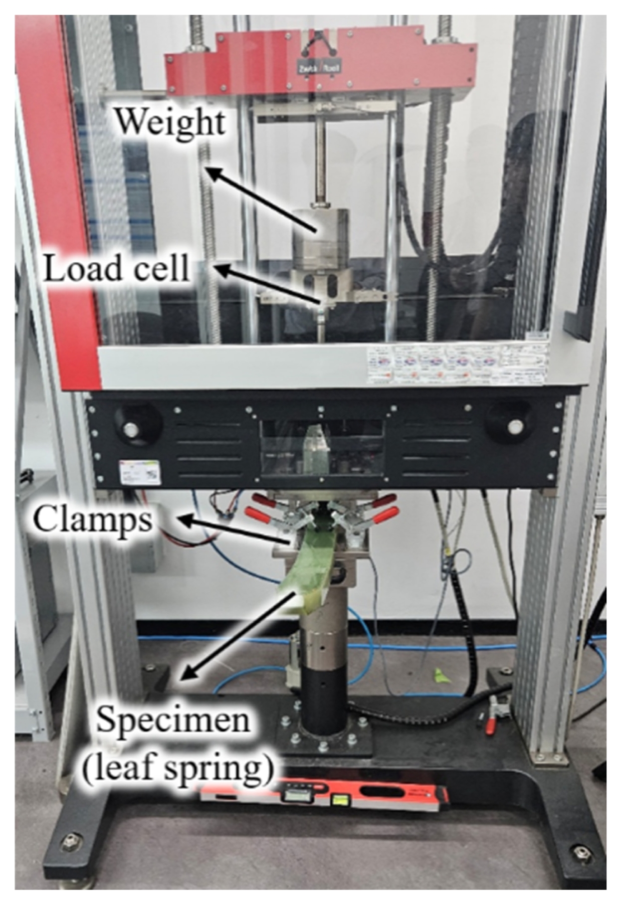
Fig. 6Impact result of 20 (left) and 80 J (right) impact energy
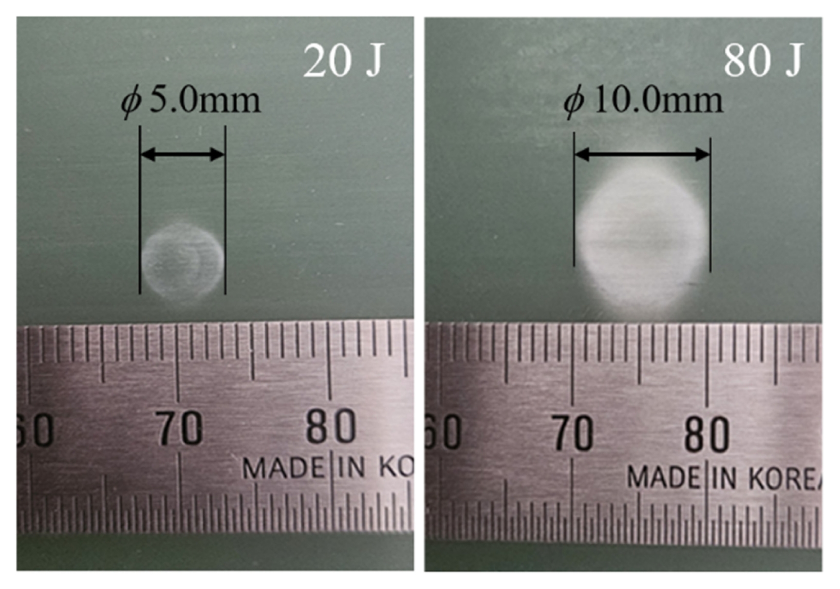
Fig. 7Setting up coordinate axes in CarSim
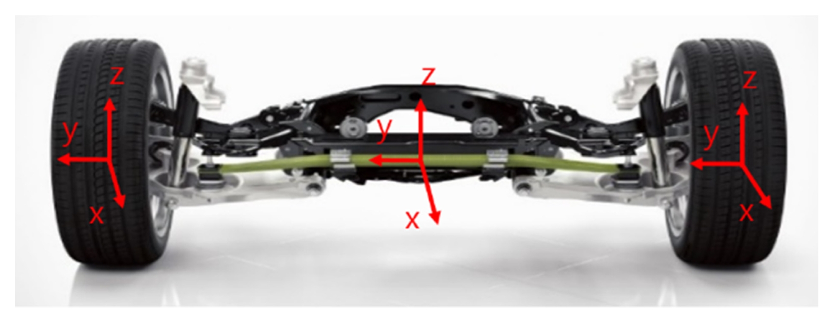
Fig. 8Driving environments conditions of each case
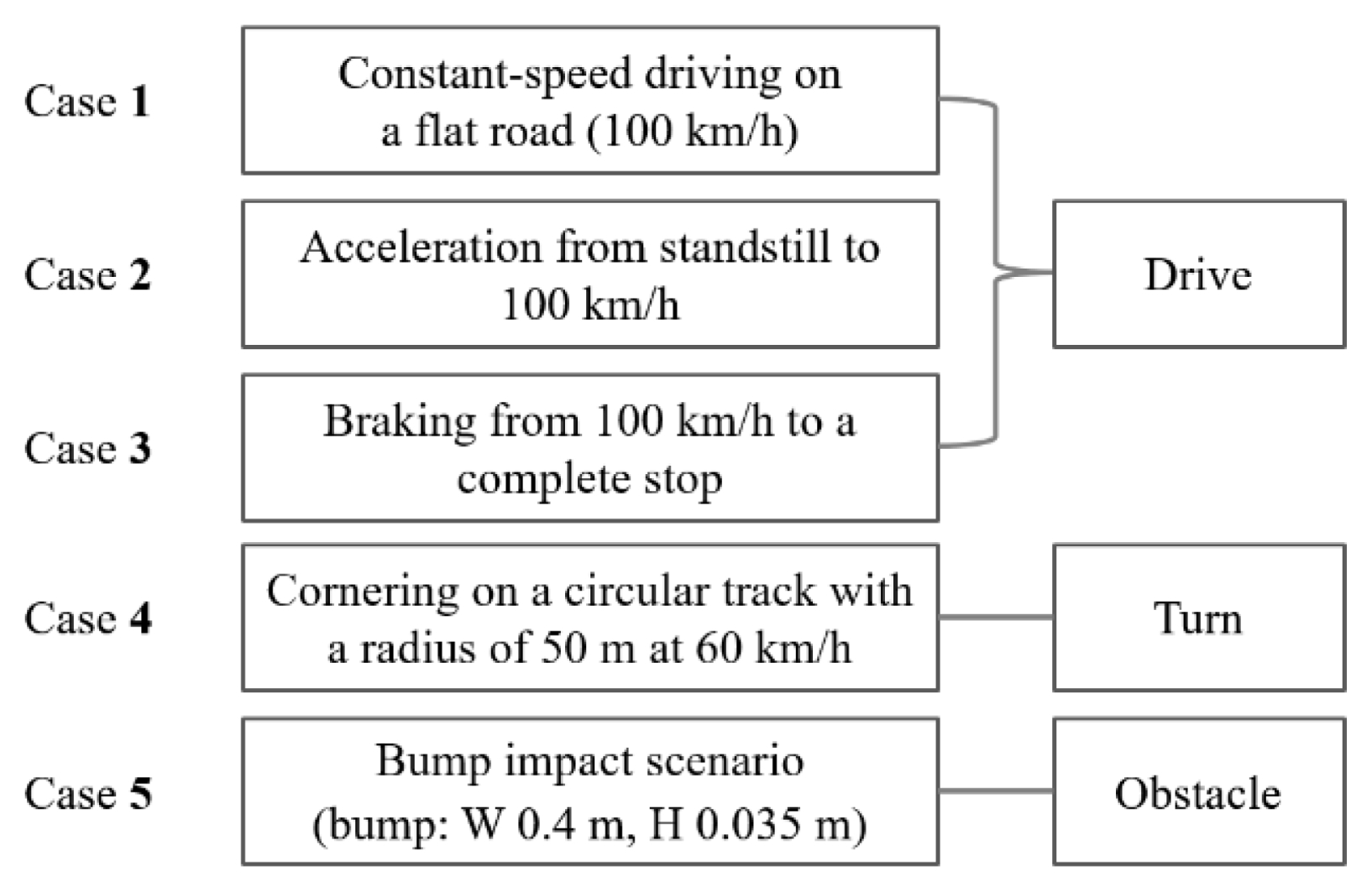
Fig. 9Leaf spring load and moment results in Case 1
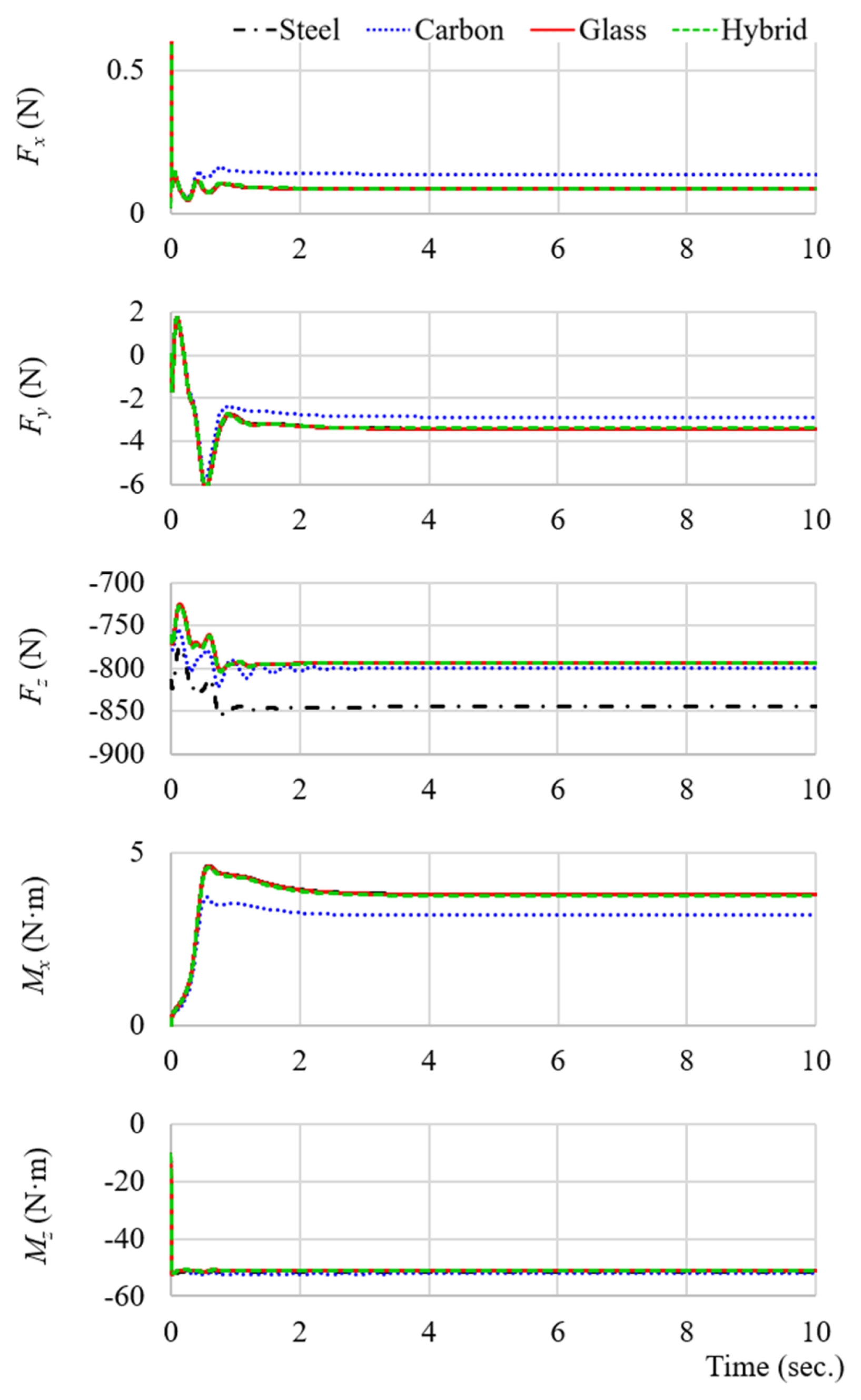
Fig. 10Leaf spring load and moment results in Case 2
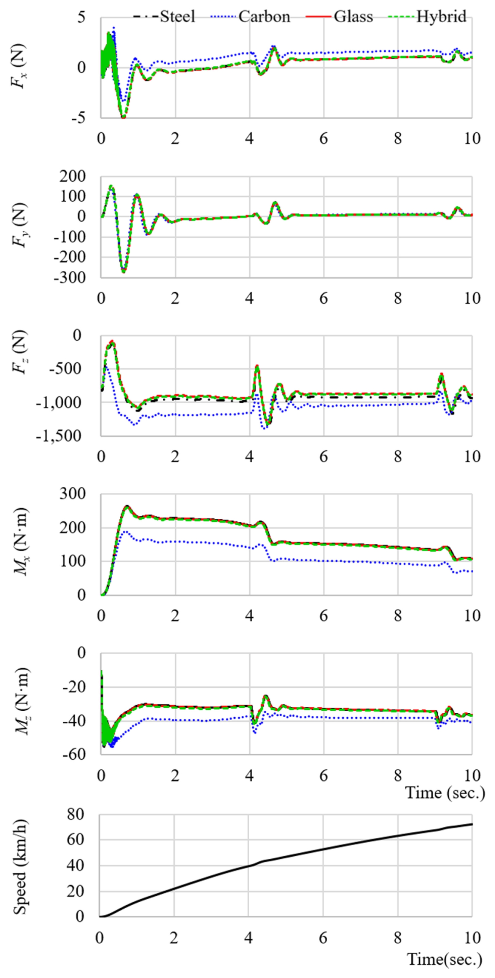
Fig. 11Leaf spring load and moment results in Case 3
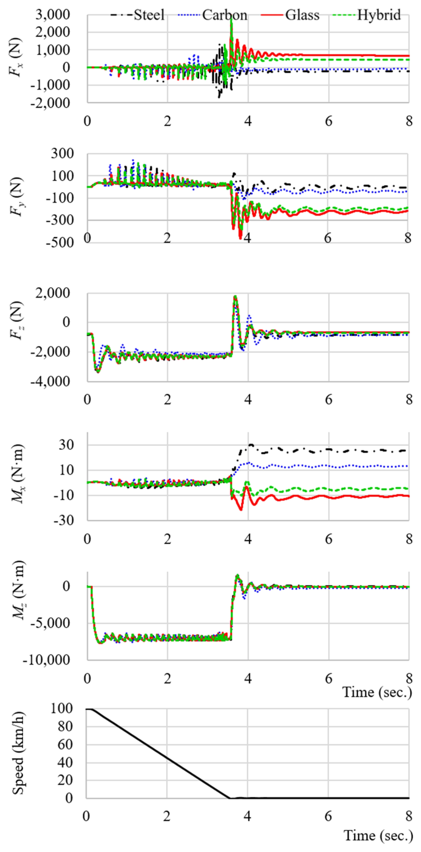
Fig. 12Leaf spring load and moment results in Case 4
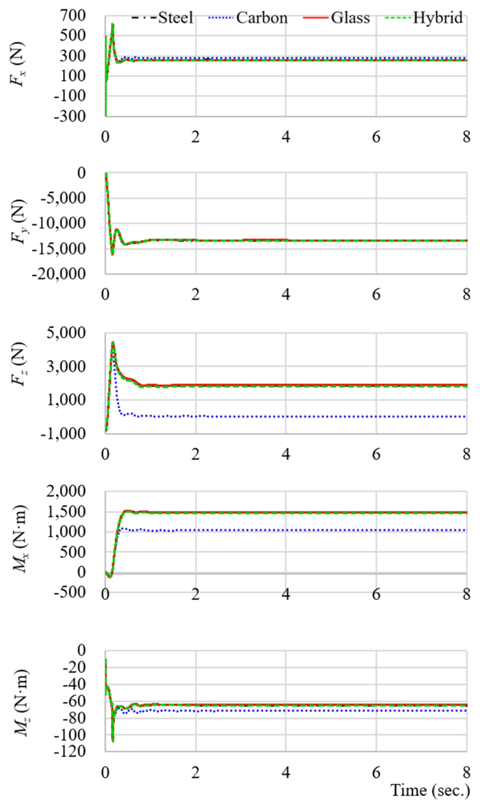
Fig. 13Leaf spring load and moment results in Case 5 (vehicle speed 120km/h)
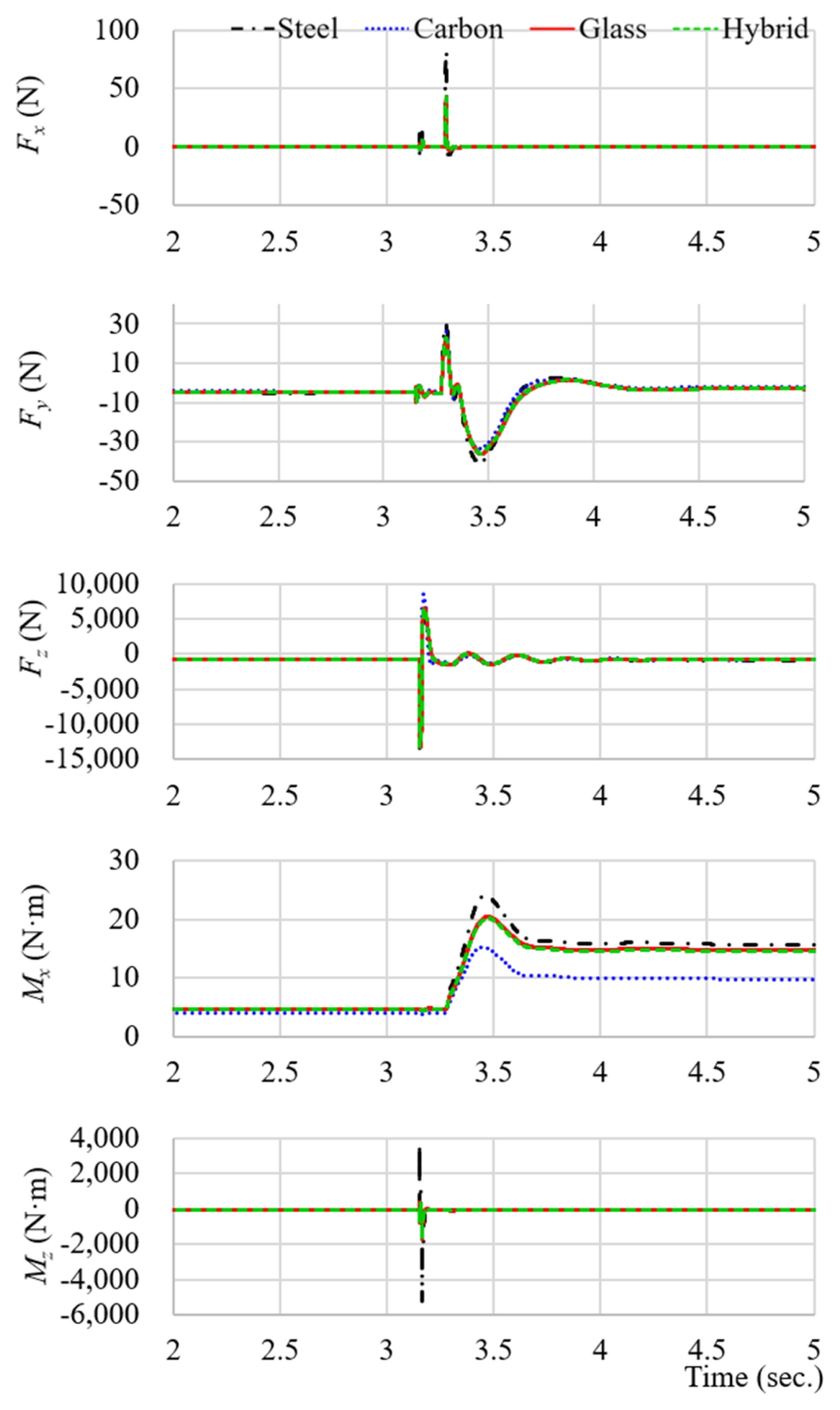
Table 1Properties of each composite material
Table 1
|
Type |
Carbon |
Hybrid |
Glass |
|
Tensile strength (Mpa)*
|
1,785.0 |
1,130.0 |
835.0 |
|
Elastic modulus (Gpa)*
|
125.0 |
52.5 |
42.4 |
|
Flexural modulus (Gpa)**
|
105.0 |
90.0 |
88.0 |
|
Mass per unit area (g/m2) |
728.3 |
901.6 |
944.9 |
Table 2Type for mechanical properties
Table 2
|
Type |
K [N/mm] |
Weight reduction [%] |
|
Steel (JIS SUP7) |
295 |
0 |
|
Carbon |
875 |
69.0 |
|
Hybrid |
315 |
63.0 |
|
Glass |
297 |
61.5 |
Table 3Summary of simulation results
Table 3
|
Case |
Composite type |
Peak vertical load [Fz (N)] |
Peak roll moment [Mx (N·m)] |
|
1 |
Carbon |
820 |
4 |
|
Glass |
800 |
5 |
|
Hybrid |
805 |
5 |
|
2 |
Carbon |
1,410 |
190 |
|
Glass |
1,290 |
260 |
|
Hybrid |
1,320 |
250 |
|
3 |
Carbon |
3,000 |
16 |
|
Glass |
3,200 |
22 |
|
Hybrid |
3,180 |
10 |
|
4 |
Carbon |
4,150 |
1,100 |
|
Glass |
4,400 |
1,530 |
|
Hybrid |
4,350 |
1,510 |
|
5 |
Carbon |
12,500 |
14 |
|
Glass |
13,400 |
20 |
|
Hybrid |
13,300 |
20 |
REFERENCES
- 1. Lee, B. R., Park, S. P., Hong, J. B., Kim, T., Shim, G., (2021), Development of light body part with complex material, Proceedings of the Spring Conference of the Korean Society of Automotive Engineers (KSAE), 566.
- 2. Pagerit, S., Sharer, P., Rousseau, A., (2006), Fuel economy sensitivity to vehicle mass for advanced vehicle powertrains, Proceedings of the SAE 2006 World Congress & Exhibition.
- 3. Moon, W.-K., Song, C.-K., (2008), Hysteretic characteristics of leaf springs in commercial vehicles, Transactions of the Korean Society of Automotive Engineers, 16(2), 99-105.
- 4. Moon, I., Oh, C., (2001), A study on the effects of hysteretic characteristics of leaf springs on handling of a large-sized truck, Journal of Korean Society of Agricultural Engineers, 9(5), 157-164.
- 5. Mallick, P. K., (2007), Fiber-reinforced composites: materials, manufacturing, and design, 3rd Edition, CRC Press.
- 6. Ju, Y. J., (2020), A study on the materials selection method for the lightweighting of automobile and improvement of fuel-conditioning performance, Ph. D. Thesis, Hongik University.
- 7. Jayan, J. S., Appukuttan, S., Wilson, R., Joseph, K., George, G., Oksman, K., (2021), AN introduction to fiber reinforced composite materials, Fiber Reinforced Composites, 1-24.
- 8. Jadee, K. J., Othman, A., (2011), Fiber reinforced composite structure with bolted joint–a review, Key Engineering Materials, 471, 939-944.
- 9. Kim, K.-S., Bae, K.-M., Oh, S.-Y., Seo, M.-K., Kang, C.-G., Park, S.-J., (2012), Trend of carbon fiber-reinforced composites for lightweight vehicles, Elastomers and Composites, 47(1), 65-74.
- 10. Suprith, N., Annamalai, K., Naiju, C., Mahadevan, A., (2013), Design and analysis of automotive multi-leaf springs using composite materials, Applied Mechanics and Materials, 372, 533-537.
- 11. Upletawala, M. A. I., Kushwaha, A., Bhawde, G., (2021), Optimization and weight reduction of hybrid composite leaf spring, Journal of Physics: Conference Series, 012036.
- 12. Kang, T.-Y., An, H.-S., Chun, H.-J., Park, J.-C., (2021), Fatigue behavior of composites with different fiber orientation, Composites Research, 34(2), 77-81.
- 13. Oh, S. H., Choi, B. L., (2014), Prediction of spring rate and initial failure load due to material properties of composite leaf spring, Transactions of the Korean Society of Mechanical Engineers A, 38(12), 1345-1350.
- 14. Pendyala, A., Krishna, C. S. R., Jagadish, C., (2021), Fatigue life of composite leaf spring assembly, IOP Conference Series: Materials Science and Engineering, 1185: 012034.
- 15. Jang, K. S., Kim, T. R., Kim, J. H., Yun, G. J., (2022), Multi-scale process-structural analysis considering the stochastic distribution of material properties in the microstructure, Composites Research, 35(3), 188-195.
- 16. Moon, I.-D., Yoon, H.-S., Oh, C.-Y., (2006), A flexible multi-body dynamic model for analyzing the hysteretic characteristics and the dynamic stress of a taper leaf spring, Journal of Mechanical Science and Technology, 20(10), 1638-1645.
- 17. Song, S. M., (2018), Optimum design of composite leaf spring using vehicle dynamics analysis, M.S Thesis, Konkuk University.
- 18. Song, W. B., Kim, Y. H., Oh, S. H., Kim, H. S., Do, H. S., (2024), Evaluation and improvement of a transversely mounted composite leaf spring suspension with integrated link function, Proceedings of the KSAE Annual Autumn Conference, 496-498.
- 19. Park, M. R., Lee, S. H., Choi, S. G., Jung, B. J., (2024), Weight Reduction and Vehicle Performance Improvement through Application of GFRP Leaf Spring in CTBA Suspension, Proceedings of the KSAE Annual Autumn Conference, 24AKSAE_C050.
- 20. ASTM D3418-21, (2021), Standard test method for transition temperatures and enthalpies of fusion and crystallization of polymers by differential scanning calorimetry.
- 21. ASTM D7136/D7136M-20, (2020), Standard test method for measuring the damage resistance of a fiber-reinforced polymer matrix composite to a drop-weight impact event.
Biography
- Se-Hyun Cho
Ph.D. candidate in the Department of Management of Technology, Gyeongsang National University and CEO of Beomhan Motors Co., Ltd. His professional interests include electric vehicles, automotive systems, and vehicle manufacturing and components.
- Gi-Seo Park
Professor in the Department of Mechanical and Automotive Engineering at the University of Ulsan, Republic of Korea. His research interests include vehicle systems control, robotics, and autonomous control systems.
- Jeong-Hwan Jeon
Professor in the School of Industrial and Systems Engineering at Gyeongsang National University. His research interests include technology innovation strategy, R&D policy analysis, and data-driven technology management for industrial competitiveness.
- Won-Shik Chu
Professor in the Department of Mechanical Convergence Engineering at Gyeongsang National University. His research interests include smart materials and actuators, soft robotics, and manufacturing processes such as precision machining and additive manufacturing (3D printing).