ABSTRACT
This paper presents a method for estimating the fatigue life of crossed roller bearings (XRBs). XRBs feature a single row of rollers arranged alternately at right angles, making them ideal for applications that require high precision and a compact design. In rolling-element bearings, fatigue life is a crucial design parameter for ensuring long-term reliability and performance. However, existing fatigue life estimation models for XRBs in the literature are limited to basic rating life, with no models available for reference rating life. To address this gap, we developed a comprehensive fatigue life prediction model specifically for XRBs. We formulated a corresponding dynamic load rating to align with the values provided by bearing manufacturers and calibrated an unknown adjustment factor for XRBs using a commercial program. Additionally, a parametric study was conducted to investigate the impact of varying diametral clearance, external loads, roller dimensions, and roller profile parameters on the fatigue life of XRBs.
-
KEYWORDS: Crossed roller bearing, Dynamic load rating, Fatigue life, Dynamic equivalent load
-
KEYWORDS: 크로스롤러베어링, 동정격하중, 피로수명, 동등가하중
NOMENCLATURE
Basic Dynamic Load Rating, N
Factor Dependent on Bearing Geometry
Stress Correction Function
External Loads/Moments, N,N-mm
Roller Profile Function, mm
Effective Roller Length, mm
Roller Flat Middle Length, mm
Basic Rating Life, 106 rpm
Reference Rating Life, 106 rpm
Reference Rating Life, hrs
Number of Slices in a Roller
Maximum Pressure at a Lamina, MPa
Basic Dynamic Equivalent Load, N
Dynamic Load Rating of One Lamina, N
Dynamic Equivalent Load of One Lamina, N
Contact Load for Basic Dynamic Load Rating, N
Inner Ring Displacement Vector, mm, rad
Roller Displacement Vector, mm, rad
Dynamic Radial Load Factor
Dynamic Axial Load Factor
Total Number of Rollers Per Row
Nominal Contact Angle, rad
Auxiliary Parameter, γ = Da/dm cosα
Inner Ring Displacement Vector, mm, rad
Rotated Angle in ξζη Coordinate System, rad
1. Introduction
A crossed roller bearing (XRB) is a bearing featuring cylindrical rollers arranged in a crisscross pattern between the inner and outer rings. Adjacent rollers are oriented 90 degrees to each other, enabling the bearing to support axial, radial, and moment loads [
1-
6]. Due to these structural characteristics, XRBs are suitable for applications requiring precise rotational movement and compact designs.
A notable contribution was made by de Mul et al. [
7,
8], who developed a five-degrees-of-freedom (DOF) model for ball and roller bearings using a modular approach. Their methodology has since been widely adopted by researchers to study the mechanical performance of double-row bearings, including analyses of stiffness, fatigue life, and frictional resistance [
9-
12], and has also been applied to double-directional bearings [
13,
14]. In addition, various alternative bearing models have been proposed by other researchers to further investigate the characteristics and performance of these complex bearing configurations [
15-
22]. Despite significant progress in rolling bearing modeling, XRBs have received comparatively limited attention, particularly regarding their fatigue life. Tong et al. [
23,
24] introduced a modular modeling approach that incorporated roller roundness errors, enabling the analysis of XRB stiffness characteristics under various loading conditions. Kang and Tesar [
25] analytically compared XRBs with four-point contact ball bearings in modular robotic applications, demonstrating the superior stiffness performance of XRBs.
The basic rating life (
L10) of a rolling bearing is defined as the number of revolutions (in millions) at which 10% of the rolling elements (balls or rollers) or inner/outer rings are expected to experience initial failure [
26-
29]. The fatigue life of rolling-element bearings is affected by multiple factors, including lubrication conditions, contamination, applied loading, internal clearance, misalignment, and temperature effects [
30-
37]. Hwang et al. [
38] conducted both numerical and experimental studies to evaluate the wear behavior of XRBs of various sizes, while Quagliato [
39] developed a run-out-based fatigue life prediction model by incorporating accelerated fatigue testing and finite element analysis.
Basic rating life is typically calculated using ISO 281 [
40]. This method applies to systems with standard axial or radial load configuration, rigid or firmly connected bearing supports, proper fitting, lubrication. However, bearing life can also be estimated as reference rating life (
L10r) using ISO/TS 16281 [
41]. Unlike
L10 in ISO 281,
L10r incorporates additional factors such as contact loads induced by external loads, bearing tilting effects, internal clearances, rolling element and race profiles, and inertial effects including centrifugal forces and gyroscopic moments [
42]. However, a standardized fatigue life model specifically for XRBs is not yet publicly available.
XRBs are characterized by a nominal contact angle of 45
o, enabling them to function as either axial or radial roller bearings depending on the application [
1]. However, the current dynamic equivalent load formulations in the ISO standard [
40] do not account for moment loading, which is an important consideration in many XRB use cases. To address this, some manufacturers [
3-
5] have proposed modified equivalent load equations for radial XRBs that include moment effects. On the other hand, a bearing company [
1] introduced a unique formulation for calculating the basic dynamic equivalent load applicable to both axial and radial XRBs. Nonetheless, these efforts focus solely on
L10 rather than
L10r, which is acknowledged as a more appropriate prediction method for fatigue life. A key limitation in estimating XRB fatigue life is the absence of a standardized formulation for
L10r, as it involves several unknown constants that must be determined. Notably, Schaeffler [
42] has developed a commercial software tool based on ISO/TS 16281 which can be used to estimate these unknown parameters and enables the calculation of
L10r for XRBs by incorporating these advanced considerations.
In this paper, we examined the L10r , as well as L10 , utilizing the basic dynamic load rating (C). The analysis was limited to cases where the bearing primarily experiences axial loads, employing the axial basic dynamic load rating (Ca ). A revised model for estimating the basic dynamic load rating was developed to match the bearing manufacturers’ catalog values. To evaluate the reference rating life, a quasi-static model for XRBs was employed. The fatigue life predictions for different large-sized XRBs were compared against manufacturer-provided data then used to calibrate unknown parameters. These parameters were incorporated into a generalized fatigue life equation for XRBs. Additionally, a parametric study was carried out to examine the effects of varying internal clearance, external loads, roller dimensions, and roller profile on L10r.
2. XRB Modeling
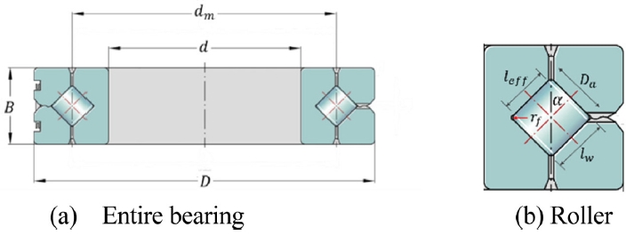
Fig. 1 shows an XRB model, including important parameters and dimensions such as the external dimensions of the bearing, the number of rollers, and the roller dimensions. In this paper, a comprehensive XRB model presented by Tong et al. [
23,
24] has been adapted. The model incorporates 5-DOF for both loading and displacement. In this study, the XRB inner ring is assumed to rotate at a speed
n, while the outer ring remains stationary.
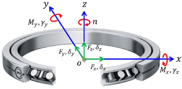
Fig. 2 shows the global coordinate system of XRB. The external loads applied to the bearing are shown, there,
Fz denotes the axial load,
Fx and
Fy are the radial loads, and
Mx and
My are the moments acting on the bearing in the x and y directions, respectively. Correspondingly, the displacements induced by these loads are defined as
δz designating the displacement on the z axis,
δx and
δy being the displacements in the
x and
y directions, and
γx and
γy representing the angular displacements (tilt) around the
x and
y axes. A summary for the quasi-static model for XRBs is presented in
Appendix A1. It offers critical insights into contact load distributions, which are essential for the fatigue life estimation.
3. Fatigue Life of XRBs
The fatigue life of a bearing is defined as the number of revolutions it can withstand before the emergence of an initial defect in either the rolling element or races. This study adopts the concept of the basic rating life and reference rating life of bearings which are calculated under appropriate lubrication conditions to represent a 90% probability of the bearing's endurance without failure [
26-
29].
The calculation of
L10 is based on a defined percentage such that a sufficiently large group of apparently identical bearings achieves or exceeds a particular number of revolutions before the first evidence of material fatigue appears with a requisite reliability of 90% [
1]. The
L10 in million revolutions, and
Lh10 in hours can be determined as:
Here,
C and
P correspond to the basic dynamic load rating and basic equivalent load, respectively. If the XRB is treated as an axial roller bearing, use
Ca and
Pa, otherwise, use
Cr and
Pr. These values will be further discussed in Section 3.3. When
C (as provided in catalogs) is known, only
P needs to be determined to estimate the basic rating life of XRBs. ISO 281 [
40] provides equations for calculating
P for various types of roller bearings, but these are limited to cases involving combined axial and radial loads. To account for additional moment loading effects, the dynamic equivalent load which is either axial (
Pₐ) or radial (
Pᵣ), can be estimated as:
Here,
Fa represents the external axial load,
Fr the external radial load,
M the applied external moment, and
dm the bearing pitch diameter. Depending on the application, X and Y factors can be determined in
Table 1.
For an axial roller bearing under pure axial loading, Pa = Fa. For a radial roller bearing under pure radial loading, Pr = Fr.
3.2 Reference Rating Life (L10r)
To evaluate
L10r, a slicing technique is applied [
10].
L10r of XRB is first calculated for each roller row with index depending on the sign of the roller (τ =
P,
N) individually (where “P” - positive roller row and “N” - negative roller row)
and then combined to yield the overall bearing life, as described by:
Here,
ns is defined as the number of slices in a roller-race contact.
qkci,
qkce denote as the dynamic load rating of one lamina
k at the inner race and outer race of one roller, respectively.
qkei,
qkee correspond to the dynamic equivalent load on a lamina
k of an inner race and outer race, respectively. For both types of XRBs, the rolling element load per lamina can be estimated by [
41]:
Here, the dynamic equivalent load per lamina of roller-race contact can be obtained from the rolling element load for the basic dynamic load ratings [
41]:
For axial roller bearings:
For radial roller bearings:
where Z represents the number of rollers per row, and
irow is the number of rows (2 for XRBs), α is the contact angle (45
o for XRBs) and
γ is defined as
Dacosα/
dm, with
Da and
dm being the roller diameter, and pitch diameter, respectively. Here, the adjustment factor
λν remains unknown, as it depends on the specific type of contact between the rollers and races [
27,
31]. This factor will be identified during the calibration phase of the proposed model, by correlating the results obtained from a commercial bearing analysis software.
The dynamic equivalent load on a lamina
k if the inner ring rotates and the outer ring is stationary can be calculated as [
40]:
Here,
qij,k and
qej,k, are the contact loads per lamina on inner race and outer race, respectively. These contact loads per lamina can be obtained as discussed in
Appendix A1. The stress correction factor for the consideration of edge load can be estimated as [
41]:
where
pHij,k and
pHej,k denote the maximum contact pressures at lamina
k for roller
j [
37] and
leff corresponds to the effective roller length.
Given the basic dimensions of the bearing, ISO 281 [
40] provides an equation to estimate the basic dynamic load rating for various types of roller bearings. The basic dynamic axial load rating is defined as a constant axial load that a rolling bearing can theoretically withstand for a basic rating life of one million revolutions given by
Similarly, the basic dynamic radial load rating refers to a constant radial load that a bearing can theoretically endure over the same rating life and is defined as
where
fc is a factor which depends on the geometry of the bearing components. This factor can be estimated as a function of
γ. The
fc table can be found in ISO 281 [
40]. On the other hand,
bm denotes the rating factor that varies with bearing type and design. However, the standard does not provide the rating factor
bm for XRBs. For accurate estimations, knowledge of the internal design of the bearings is prerequisite and therefore recommended that basic dynamic load rating,
Cr or
Ca, if available, should be obtained from the bearing manufacturers’ catalogues [
41].
4. Model Validation and Parameter Identification
The proposed reference rating life model was validated by comparing the contact load results with a commercial program [
42]. A parameter identification for basic dynamic axial load rating was made to match with manufacturer’s catalog dynamic load rating. The identification procedure for
bm in Eq. (17) is summarized in
Appendix B. Then, an adjustment factor
λν was identified from a commercial program’s results.
The selected bearing for validation was the XRB model SX011880, which was assumed to be subjected to pure axial loads ranging from
Fz = 1-50 kN. The bearing was assumed to operate at a speed of 1,000 rpm. Detailed specifications of the investigated XRB are provided in
Table 2.
Contact loads are crucial factors in estimating the reference rating life
L10r of rolling bearings.
Fig. 3 compares the results obtained using the current quasi-static model and those from the commercial software [
42]. As shown in
Fig. 3(a), the contact loads of the positive and negative rows increase and decrease linearly, respectively, with increasing axial load. The positive row experiences higher loads as axial load increases, while the negative row exhibits a reduction in contact load, reflecting the directional nature of XRBs. The current model (solid blue line) shows strong agreement with the reference values (red square markers) across the full range of applied loads. Further validation is presented in
Fig. 3(b), which illustrates the variation of axial and radial stiffness with axial load. Both stiffness components gradually decrease as the axial load increases, indicating softening behavior. Notably, both stiffness show a steeper decline beyond approximately 50 kN, due to the loss of contacts of the negative rollers with the inner race.
To estimate both
L10 and
L10r, the basic dynamic axial load rating must be determined. As given in
Appendix B, the rating factor was estimated as
bm ≈ 1.08013. By plugging it to Eq. (17), the dynamic load rating can be calculated as
Ca = 385,124 N which has around 0.03% error compared to the reported value in
Table 2. This resultant
Ca is used to identify unknown parameters for
L10r.
While the proposed model accurately reproduces the contact loads and basic dynamic load ratings, an empirical adjustment factor, denoted as
λν, remains necessary for accurately estimating the reference rating life. As discussed in Ref. [
27,
31],
λν is associated with the type of contact between the rollers and raceways, reflecting complex stress distributions and material behavior not captured in basic formulations.
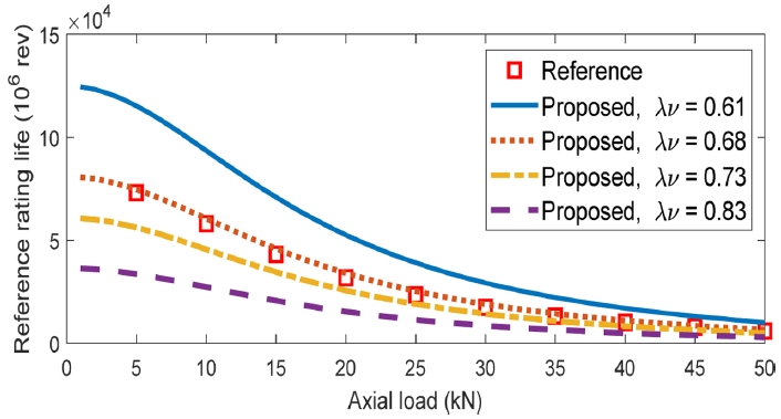
Fig. 4 presents the reference rating life of the XRB as a function of axial load, comparing results from the proposed model with those obtained from a commercial software (represented by red square markers) with different adjustment factors provided by ISO standard [
41] and Harris [
31]. To determine a suitable value for this parameter, several
λν values were evaluated with the proposed model. The results indicate a clear trend: increasing
λν leads to a decrease in predicted reference life across all axial load levels. Additionally, the fatigue life shows a nonlinear decrease with increasing axial load, as expected. Among the tested values,
λν = 0.68 yields the closest match to the reference life data from the commercial program. This value was adopted as a representative constant for axial XRB configurations under similar loading conditions. The analysis also highlights the model’s sensitivity to this factor, emphasizes the importance of accurately calibrating
λν when using reference rating life models for accurate fatigue life assessment of XRBs.
5. Simulations and Discussions
This section presents the simulation results for the fatigue life of XRBs, starting with a comparative analysis between the basic rating life and the reference rating life.
5.1 Comparison of L10 and L10r
Table 3 presents a comparison between the
L10 and the
L10r of the XRB under two different axial load conditions and diametral preloads. At a relatively low axial load of 1,000 N with original diametral preload of -15 μm, the basic rating life is 4.16 × 10
8 (million revolutions), while the reference rating life is significantly lower as 8.06 × 10
4 (million revolutions). Such a big difference indicates that the
L10 model, because it does not account for important factors such as internal load distribution. which is mainly dependent on internal clearance, and roller/race profiles, tends to substantially overestimate bearing life. At a higher load of 10,000 N, the difference narrows but remains still significant. When the diametral preload is set to 0 μm under 1000 N axial load, the reference rating life drastically increased to 2.58 × 10
9 (million revolutions) which even exceeded the calculated basic rating life.
This improvement for
L10r may come from a better design parameter such as better material and better roller/race profile. The same trend also happens under relatively high axial load which
L10r improved to 1.72 × 10
6 (million revolutions).
Table 3 also shows the corresponding diametral preloads that give
L10r a close match with
L10 indicating that certain amount of diametral preload is needed to achieve the reported basic rating life.
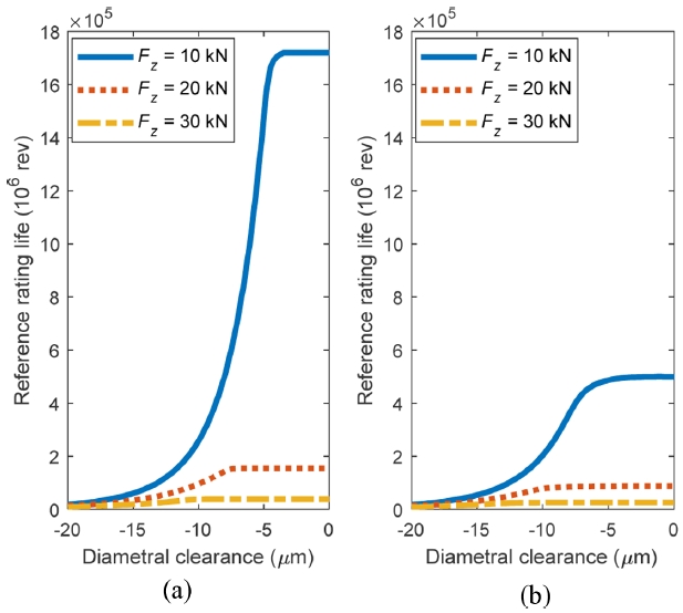
Fig. 5 shows the variation in
L10r as a function of diametral clearance (-20 μm to 0 μm) under axial loads of 10, 20, and 30 kN, both with and without radial load. In
Fig. 5(a) under pure axial loads,
L10r increases significantly as clearance decreases under 10 kN, with a sharp nonlinear rise near zero clearance. This reflects improved roller engagement, stress concentrations, and load sharing due to favorable preload. At 20 kN, the increase is milder, while at 30 kN, life remains nearly constant and low, as higher stress concentrations reduce the benefit of preload. As clearance approaches zero,
L10r tends to plateau, especially under higher loads, because fewer rollers carry the load; the rollers in the negative row lose contact or become lightly loaded, concentrating stress on fewer rollers and limiting life improvement.
In
Fig. 5(b) under combined axial and radial load,
L10r drops across all load cases, and the beneficial effect of reduced clearance is diminished. The radial load induces asymmetric contact, accelerating roller disengagement and reducing effective load sharing. This effect is most pronounced at 10 kN, where the drastic rise in
L10r near zero clearance becomes more gradual and saturates earlier. At 20 and 30 kN, life remains nearly constant throughout, indicating that the radial load suppresses the clearance-dependent improvement by reducing roller engagement.
Fig. 6 presents the variation in reference rating life of an XRB as a function of axial load, evaluated under three different constant radial loads. The key difference between the two subfigures lies in the assumed diametral clearance:
Fig. 6(a) corresponds to a preloaded condition (-15 μm), while 6(b) represents a zero-clearance condition. In
Fig. 6(a),
L10r decreases rapidly with an increasing axial load, especially in the absence of radial load. This reduction is due to higher contact stresses and a higher roller load distribution. Under low axial loads, preload promotes more uniform roller engagement, resulting in relatively high life. However, introducing radial load shifts the curves downward across all axial load levels, as the added radial component increases overall stress and induces asymmetric contact, leading to earlier roller disengagement around the opposite direction of the radially loaded rollers.
In
Fig. 6(b), a similar trend is observed, but
L10r starts at a much higher value under low axial load, particularly in the
Fx = 0 kN case. This reflects the optimal contact conditions at zero clearance, where most rollers are uniformly engaged. A logarithmic vertical axis is used to better capture the wide range in life values. Despite the higher starting point,
L10r deteriorates sharply with increasing axial load, and radial load (
Fx = 5 and 10 kN) also significantly reduces life, with the curves converging at higher axial loads. Comparing
Figs. 6(a) and
6(b), it is evident that zero clearance offers a greater enhancement in fatigue life, particularly at low axial loads and in the absence of radial load. However, as axial and/or radial loads increase, this advantage diminishes, and bearing life becomes increasingly governed by the combined stress state rather than internal clearance alone.
Fig. 7 shows the influence of roller length (and, equivalently, roller diameter) on the reference rating life, evaluated across a range of axial loads from 5 to 30 kN. In this parametric study, the roller length varies from 10 to 30 mm, and the same dimensional change is applied to the roller diameter, maintaining a constant aspect ratio. The results indicate a strong positive correlation between roller size and reference rating life, with life increasing nonlinearly as roller length increases. This behavior is attributed by the larger effective contact area and improved load distribution offered by longer rollers, which eventually reduce localized stress and extend fatigue life. The impact of roller geometry is particularly pronounced at lower axial loads. However, as axial load increases, the slope of the life curve diminishes, and the beneficial effect of increasing roller size becomes less effective. At
Fz = 30 kN, although fatigue life still increases with roller size, the overall magnitude is moderately increasing. These results highlight that enlarging roller dimensions is especially effective under moderate-to-low loading conditions, while at high axial loads, the benefit becomes limited due to stress saturation and potential edge loading effects. To further enhance visualization and interpretation, a 3D plot is included, showing the combined influence of axial load and roller length on
L10r . The plot clearly reveals the nonlinear and load-sensitive behavior of life, reinforcing the observation that roller geometry plays a more dominant role under moderate-to-light axial loads.
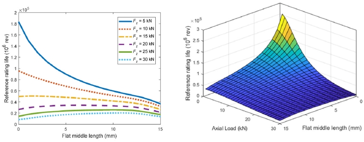
5.5 Effect of Flat Middle Length Change
Fig. 8 explores the effect of the roller profile's flat middle length on
L10r under varying axial loads. As shown in
Fig. 8, shorter flat lengths enhance crowning effectiveness, helping compensate for misalignments and reducing edge stresses, which results in significantly higher fatigue life, especially under moderate-to-low axial loads. In contrast, longer flat length region makes the fatigue life resemble that of cylindrical rollers, because of causing contact pressure to concentrate on the edges and degrade life performance due to uneven load distribution.
At low loads, L10r decreases monotonically with increasing flat length. However, for higher loads (Fz = 20-30 kN), the trend becomes non-monotonic, here, life initially increases with flat length, reaches a peak, and then declines. This indicates that under heavy axial loading, a moderate flat region can improve life by reducing peak contact stress and achieving a more uniform stress distribution. Nevertheless, when the flat length becomes too long, stress again localizes near the edges, diminishing the benefit. A 3D plot of L10r as a function of axial load and flat middle length is also presented, clearly highlighting this interaction.
6. Concluding Remarks
A fatigue life model for crossed roller bearings (XRBs) was developed along with a quasi-static model to evaluate internal load distribution under combined axial and radial loading. The key findings are summarized as follows:
1) Reference rating life is highly sensitive to diametral clearance, especially under low axial loads. Reducing clearance significantly improves life due to more uniform load distribution.
2) The presence of radial load leads to earlier roller disengagement and flattens the life curve, particularly under high axial loads.
3) Reference rating life decreases with increasing axial load. This decay is more severe at small clearance, where life is initially high but rapidly drops due to increased contact stress.
4) Increasing roller length (or diameter) improves bearing life, especially under low axial loads. The effect diminishes as axial load increases due to edge stress concentrations.
5) Longer flat middle lengths reduce fatigue life, while shorter flat regions enhance life by mitigating edge stresses, particularly under low-to-moderate loads.
FOOTNOTES
-
ACKNOWLEDGEMENT
This work was supported by the Weapon System Component Localization Grant, funded by the Korea Research Institute for Defense Technology Planning and Advancement (KRIT) (No. C220012).
Fig. 1Cross sectional views of a XRB with important dimensions

Fig. 2

Fig. 3Contact load and stiffness comparison with commercial program, n = 1000 rpm, a) contact loads, b) stiffness
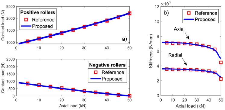
Fig. 4Reference rating life as a function of axial load with changing adjustment factor λν, n = 1000 rpm

Fig. 5Reference rating life as a function of diametral clearance, (a) pure axial load and (b) combined axial and radial load, Fx = 5 kN

Fig. 6Reference rating life as a function of axial load, n = 1000 rpm, (a) Pd = -15 μm and (b) Pd = 0 μm
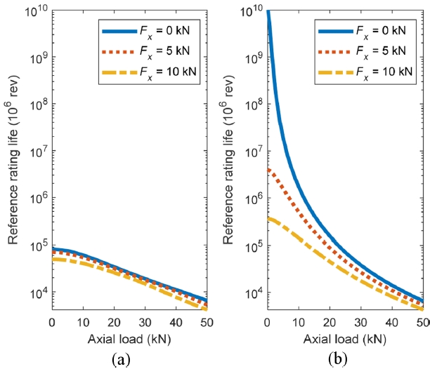
Fig. 7Reference rating life as a function of roller length, n = 1,000 rpm, Pd = -15 μm
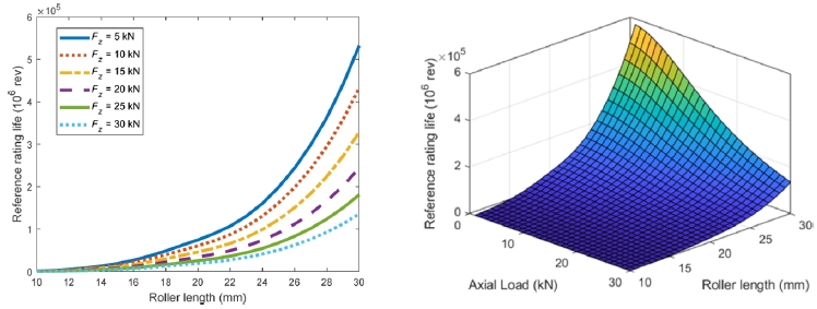
Fig. 8Reference rating life as a function of roller flat middle length, n = 1,000 rpm, Pd = -15 μm

Table 1
Table 1
Axial bearing
|
Criterion |
Radial bearing
|
|
X |
Y |
X |
Y |
|
1.5 |
0.67 |
Fa /(Fr + 2M/dm) ≤ 1.5 |
1 |
0.45 |
|
1 |
1 |
Fa /(Fr + 2M/dm) > 1.5 |
0.67 |
0.67 |
Table 2Basic p arameters of investigated XRB
Table 2
|
Bore diameter [mm] |
400 |
Roller diameter [mm] |
20 |
|
Outer diameter [mm] |
500 |
Roller length [mm] |
20 |
|
Width [mm] |
46 |
Effective length [mm] |
18.993 |
|
Pitch diameter [mm] |
450 |
Nominal contact angle [°] |
45 |
|
Number of rollers/row |
32 |
Flat middle length [mm] |
7 |
|
Basic dynamic load rating [N] |
385,000 |
Diametral preload [mm] |
-0.015 |
Table 3Comparison of basic rating life and reference rating life
Table 3
|
Axial load [N] |
Pd [µm] |
L10 [106 rev] |
L10r [106 rev] |
|
1,000 |
-15 |
4.1559 × 10⁸
|
8.0636 × 10⁴
|
|
-2 |
4.2142 × 10⁸
|
|
0 |
2.5833 × 10⁹
|
|
10,000 |
-15 |
1.9290 × 10⁵
|
6.0551 × 10⁴
|
|
-11 |
1.8845 × 10⁵
|
|
0 |
1.7196 × 10⁶
|
REFERENCES
- 1. INA-Schaeffler KG, (2003), Crossed Roller Bearings for High Precision Applications. https://www.schaeffler.de/remotemedien/media/_shared_media/08_media_library/01_publications/schaeffler_2/publication/downloads_18/ksx_de_en.pdf.
- 2. Kaydon, Catalog 390. https://www.kaydonbearings.com/downloads/catalog390/Kaydon_Catalog_390.pdf.
- 3. HIWIN Technologies Corp., (2019), Crossed roller bearings technical information, 4th ed., HIWIN Technologies Corp., Taiwan. https://www.hiwin.com/wp-content/uploads/crossed_roller_bearings-e-1.pdf.
- 4. THK, Cross-roller ring THK catalog. https://rmkmechatronik.de/wp-content/uploads/2024/12/THK-Cross-Roller-Ring-Catalog.pdf.
- 5. IKO, Crossed roller bearings, Nippon Thompson Co., Ltd.. https://www.ikont.eu/files/Documents/Catalogues/CAT-57151UKv3_IKO_CRB.pdf.
- 6. Hyun, J.-S., Kim, S.-H., (2023), Roller for cross roller bearing and cross roller bearing equipped with the same, KR1020230048671.
- 7. de Mul, J. M., Vree, J. M., Maas, D. A., (1989), Equilibrium and associated load distribution in ball and roller bearings loaded in five degrees of freedom while neglecting friction-Part I: general theory and application to ball bearings, ASME Journal of Tribology, 111(1), 142-148.
- 8. de Mul, J. M., Vree, J. M., Maas, D. A., (1989), Equilibrium and associated load distribution in ball and roller bearings loaded in five degrees of freedom while neglecting friction-Part II: application to roller bearings and experimental verification, ASME Journal of Tribology, 111(1), 149-155.
- 9. Tong, V.-C., Hong, S.-W., (2017), Modeling and analysis of double-row cylindrical roller bearings, Journal of Mechanical Science and Technology, 31(7), 3379-3388.
- 10. Tong, V.-C., Hong, S.-W., (2017), Analysis of the stiffness and fatigue life of double-row angular contact ball bearings, Journal of the Korean Society for Precision Engineering, 34(11), 813-821.
- 11. Zheng, J., Ji, J., Yin, S., Tong, V.-C., (2020), Internal loads and contact pressure distributions on the main shaft bearing in a modern gearless wind turbine, Tribology International, 141, 105960.
- 12. Kim, T. Y., Goo, J. H., Rivera, G., (2025), Study on the characteristics of spherical roller bearings, Proceedings of the KSPE 2025 Spring Conference, 290.
- 13. Rivera, G., Tong, V.-C., Hong, S.-W., (2022), Contact load and stiffness of four-point contact ball bearings under loading, International Journal of Precision Engineering and Manufacturing, 23(6), 677-687.
- 14. Sa, J. H., Kim, D. H., Rivera, G., Hong, S. W., (2024), Study on the characteristics of split-outer-ring three-point contact ball bearings subjected to combined loads, Journal of the Korean Society of Manufacturing Technology Engineers, 33(1), 35-43.
- 15. Lim, T. C., Singh, R., (1990), Vibration transmission through rolling element bearings, Part I: Bearing stiffness formulation, Journal of Sound and Vibration, 139(2), 179-199.
- 16. Gunduz, A., Singh, R., (2013), Stiffness matrix formulation for double row angular contact ball bearings: Analytical development and validation, Journal of Sound and Vibration, 332(22), 5898-5916.
- 17. Gunduz, A., Dreyer, J. T., Singh, R., (2012), Effect of bearing preloads on the modal characteristics of a shaft-bearing assembly: Experiments on double row angular contact ball bearings, Mechanical Systems and Signal Processing, 31, 176-195.
- 18. Petersen, D., Howard, C., Sawalhi, N., Ahmadi, A. M., Singh, S., (2015), Analysis of bearing stiffness variations, contact forces and vibrations in radially loaded double row rolling element bearings with raceway defects, Mechanical Systems and Signal Processing, 50, 139-160.
- 19. Zhuo, Y., Zhou, X., Yang, C., (2014), Dynamic analysis of double-row self-aligning ball bearings due to applied loads, internal clearance, surface waviness and number of balls, Journal of Sound and Vibration, 333(23), 6170-6189.
- 20. Geng, K., Lin, S., (2020), Effect of angular misalignment on the stiffness of the double-row self-aligning ball bearing, Proceedings of the Institution of Mechanical Engineers, Part C: Journal of Mechanical Engineering Science, 234(4), 946-962.
- 21. Lin, S., Jiang, S., (2019), Study of the stiffness matrix of preloaded duplex angular contact ball bearings, Journal of Tribology, 141(3), 032204.
- 22. Guo, Y., Parker, R. G., (2012), Stiffness matrix calculation of rolling element bearings using a finite element/contact mechanics model, Mechanism and Machine Theory, 51, 32-45.
- 23. Tong, V.-C., Jung, E.-W., Hong, S.-W., (2020), Modeling of crossed roller bearings considering roller roundness deformation, Journal of Tribology, 142(12), 121201.
- 24. Tong, V.-C., Hong, S.-W., (2022), Stiffness characteristics of crossed roller bearings with roller roundness deformation, Journal of Tribology, 144(2), 021201.
- 25. Kang, S.-H., Tesar, D., (2003), An analytical comparison between ball and crossed roller bearings for utilization in actuator modules for precision modular robots, Proceedings of the International Design Engineering Technical Conferences and Computers and Information in Engineering Conference, 1221-1230.
- 26. Lundberg, G., Palmgren, A., (1952), Dynamic Capacity of Roller Bearings, ACTA Polytechnica, Mechanical Engineering Series, Royal Swedish Academy of Engineering Sciences, 2(4), 96-127.
- 27. Harris, T. A., (2001), Rolling bearing analysis, 4th Ed., Wiley.
- 28. Hong, S.-W., Tong, V.-C., (2016), Rolling-element bearing modeling: A review, International Journal of Precision Engineering and Manufacturing, 17(12), 1729-1749.
- 29. Kumar, N., Satapathy, R., (2023), Bearings in aerospace, application, distress, and life: A review, Journal of Failure Analysis and Prevention, 23(3), 915-947.
- 30. Palmgren, A., (1959), Ball and roller bearing engineering, 3rd Ed., SKF Industries.
- 31. Harris, T. A., Kotzalas, M. N., (2006), Rolling bearing analysis, Essential concepts of bearing technology, 5th Ed., Taylor & Francis.
- 32. Harris, T. A., Kotzalas, M. N., (2006), Rolling bearing analysis, Advanced concepts of bearing technology, 5th Ed., Taylor & Francis.
- 33. Zaretsky, E.V., (1992), STLE life factors for rolling bearings, Society of Tribologists and Lubrication Engineers.
- 34. Oswald, F. B., Zaretsky, E. V., Poplawski, J. V., (2014), Effect of roller geometry on roller bearing load–life relation, Tribology Transactions, 57(5), 928-938.
- 35. Kim, T., Suh, J., Lee, J., Lee, B., Yu, Y., (2023), Fatigue life prediction of double-row tapered roller bearings considering thermal effect, Advances in Mechanical Engineering, 15(2), 16878132231154099.
- 36. Wang, Z., Wu, Q., Chang, Z., Yu, Q., (2024), Modeling of double-row cylindrical roller bearing under combined loads and angular misalignment, Journal of Tribology, 146(11), 114301.
- 37. Tong, V.-C., Kwon, S.-W., Hong, S.-W., (2017), Fatigue life of cylindrical roller bearings, Proceedings of the Institution of Mechanical Engineers, Part J: Journal of Engineering Tribology, 231(5), 623-636.
- 38. Hwang, S. Y., Lee, N. R., Kim, N., (2015), Experiment and numerical study of wear in cross roller thrust bearings, Lubricants, 3(2), 447-458.
- 39. Quagliato, L., Kim, D., Lee, N., Hwang, S., Domblesky, J., Kim, N., (2017), Run-out based crossed roller bearing life prediction by utilization of accelerated testing approach and fe numerical models, International Journal of Mechanical Sciences, 130, 99-110.
- 40. ISO 281:2007, (2007), Rolling bearings- dynamic load rating and rating life.
- 41. ISO/TS 16281:2008, (2008), Rolling bearings - methods for calculating the modified reference rating life for universally loaded bearings.
- 42. Schaeffler, Bearinx-online easy calculation modules. https://medias.schaeffler.de/en/bearinx.
Biography
- Gilbert Rivera
Postmaster Researcher in Kumoh National Institute of Technology (KIT). His research interests are Bearing modeling and Rotor Dynamics.
- Dong-Hyeok Kim
M.E. Candidate in Mechanical Engineering at Kumoh National Institute of Technology (KIT). His research interest is Bearing Modeling and Analysis.
- Dong Uk Kim
Researcher in Electronic Component Development Group, Korea Research Institute for Defense Technology Planning and Advancement (KRIT). His research interests incluude Computational Fluid Dynamics and Development of Defense Industry.
- Seong-Wook Hong
Professor in the Department of Mechanical System Engineering of Kumoh National Institute of Technology. His current research interests include Spindle and Bearings Modeling and Analysis, Command Shaping for Positioning Systems, Vibration Control, and Structural Vibration Analysis for Mechanical Systems.
Appendix